Chapter 8 Removing and Installing Miscellaneous Assemblies
This chapter describes how to remove and install miscellaneous assemblies within the system. For a list of part numbers for field-replaceable units and optional equipment, see "Illustrated Parts Breakdown".
Tasks covered in this chapter include:
How to Remove the Fan Tray Assembly
Before You Begin
Complete these tasks:
What to Do
-
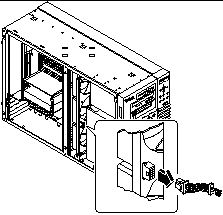
Disconnect the fan tray cable from the fan tray assembly.
Press the tab to release the connector.
Figure 8-1
-
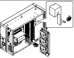
Deflect the tab that secures the fan tray in the upper guide.
-
Slide the fan tray out of the system.
Hold the tray at the center so it pulls out evenly.
Figure 8-2
What Next
To replace the fan tray assembly, complete this task:
How to Install the Fan Tray Assembly
What to Do
-
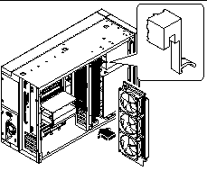
Align the fan tray assembly with the upper and lower fan tray guides.
Hold the fan tray so that the arrow on its outer edge is facing up.
-
Slide the fan tray into the top and bottom guides.
Hold the tray at the center so that the tray slides into the guides evenly.
Figure 8-3
-
Continue to push the fan tray assembly until the deflecting tab locks and the assembly is held securely in the guides.
-
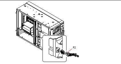
Connect the fan tray cable to the fan tray assembly.
Connect the end of the cable that is labeled P2. The connector is keyed and attaches in only one way. Press the connector until the tab locks the cable in place.
Figure 8-4
What Next
To reassemble the system, complete this task:
How to Remove a Power Supply
Before You Begin
It is not necessary to power off the system if you are removing a redundant power supply. For more information see:
If your system has only one power supply, complete this task:
What to Do
-
Identify the power supply to be removed.
-
Unplug both ends of the AC power cord.
There is no need to remove the power cord from the strain-relief tie-wrap attached to the system rear panel.
-
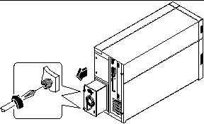
Loosen the two captive screws securing the power supply to the chassis.
Figure 8-5
-
Grasp the handle and carefully pull the power supply out of the chassis.
Be careful to disconnect the power supply in a smooth motion.
Note -When removing a "hot-pluggable" power supply, do not disengage and reengage the supply in rapid succession. Always remove a supply completely before reinserting the same supply or a replacement supply. Rapid seating and unseating of power supplies will result in false error conditions.
-
If you are not replacing the power supply immediately, install a power supply filler panel.
The filler panel is needed to maintain proper system cooling and prevent electromagnetic interference.
What Next
To replace a power supply, complete this task:
How to Install a Power Supply
Before You Begin
If you are installing a redundant power supply, it is not necessary to power off the system.
For more information, see:
What to Do
-
If you are upgrading your system with an additional power supply, remove the filler panel covering the power supply bay:
-
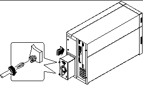
Slide the new power supply into the power supply bay until the power supply connectors start to engage the connectors on the power distribution board.
Figure 8-6
-
Push on the power supply handle to firmly engage the connectors with the power distribution board.
Press firmly to engage the power supply connectors. If you are "hot-plugging" a redundant supply, take care to avoid jarring or shocking the system.
Note -When installing a "hot-pluggable" power supply, do not engage and disengage the supply in rapid succession. Always remove a supply completely before reinserting the same supply or a replacement supply. Rapid seating and unseating of power supplies will result in false error conditions.
-
Tighten the two captive screws that secure the power supply to the chassis.
-
Connect the AC power cord to both the power supply and an AC power outlet.
Secure the cord to the rear panel with the strain-relief tie-wrap.
What Next
Verify correct operation of the power supply by checking the fan and LED indicators on the rear of the supply. The fan should start spinning and both LEDs should light within three seconds of completing a hot-plug installation (or after restoring power to the system).
For more information, see:
Note -
The power supply retains its last power on/off state once it is removed from the system. If you remove a power supply from a system that is powered off and attempt a hot-plug installation into a system that is powered on, the power supply will remain off. To activate the power supply, turn the front panel keyswitch from the Power-On position to the Diagnostics position, and then back to the Power-On position. Alternatively, you may press the Power-On key on a Sun Type-5 keyboard attached to the system. For descriptions of the various keyswitch settings, see "About the Status and Control Panel".
How to Remove the LED/Keyswitch Assembly
Before You Begin
Complete these tasks:
Video Demonstration
Figure 8-7

Click on the icon above for a video demonstration.
Click here for Appendix E, Video Player Help.
What to Do
-
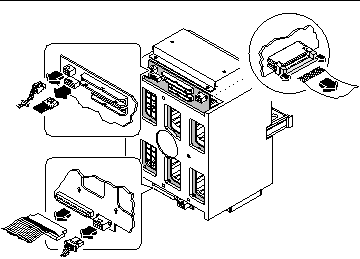
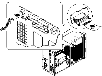
Disconnect the LED/keyswitch assembly cables from the UltraSCSI backplane:
-
Disconnect the keyswitch cable from connector J0601.
This connector is located at the upper-left corner of the backplane (as viewed from the rear).
-
Disconnect the LED ribbon cable from connector J0602 at the front of the UltraSCSI backplane.
This connector is located in the upper-left corner of the backplane (as viewed from the front). Lift the thin collar at the top of the connector to disconnect the cable. Take note of how the cable is routed.
-
-
Detach the LED ribbon cable from the underside of the removable media shelf.
Note -At the front-left corner of the system, the LED ribbon cable is secured to the underside of the removable media shelf with double-sided adhesive tape. Carefully pull the cable downward to detach it from the shelf. Reach in through the side of the chassis or open the disk access door for better access to the cable.
Figure 8-8
-
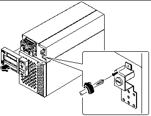
Pull off the RMA plastic cover from the front of the removable media assembly.
Grasp both sides of the cover and pull it away from the front of the system.
-
Remove the Phillips screw that secures the LED/keyswitch assembly to the front of the chassis.
Figure 8-9
-
Pull the top part of the assembly away from the chassis and lift the bottom tab free from the slot in the chassis wall.
-
Carefully pull the assembly and its attached cables out through the openings in the chassis wall.
Open the disk access door, if necessary, to gain better access to the LED ribbon cable.
What Next
To replace the LED/keyswitch assembly, complete this task:
How to Install the LED/Keyswitch Assembly
Video Demonstration
Figure 8-10

Click on the icon above for a video demonstration.
Click here for Appendix E, Video Player Help.
What to Do
-
Unlock the disk access door and swing it open.
-
Grasp the cables attached to the LED/keyswitch assembly and feed them through the appropriate openings in the front of the chassis.
Feed the keyswitch cable through the small round opening and the LED ribbon cable through the rectangular opening below it.
-
Route the keyswitch cable straight back toward the UltraSCSI backplane.
-
Thread the LED ribbon cable straight down behind the chassis wall and pull it out through the disk bay opening.
-
Insert the bottom portion of the LED/keyswitch assembly into the rectangular opening at the front of the chassis.
Position the assembly so that the bottom tab rests inside the chassis.
-
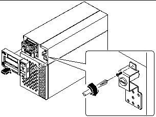
Replace the Phillips screw that secures the top portion of the assembly to the chassis wall.
-
Reattach the RMA plastic cover to the front of the removable media assembly.
Align the clips on either side of the cover with the small rectangular slots in the chassis wall. Push evenly on both sides of the cover to secure it to the chassis.
Figure 8-11
-
Grasp the corner of the LED ribbon cable, and fold the cable under itself, so that the label at the end is facing up.
Make sure that the adhesive strip at the corner of the cable is also facing up.
-
Feed the end back into the disk bay opening and route it on top of the disk cage toward the upper-left corner of the UltraSCSI backplane.
Arrange the middle portion of the cable so that it lies flat across the top of the disk cage at the front of the chassis.
-
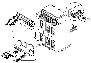
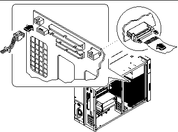
Connect the LED ribbon cable to connector J0602 on the UltraSCSI backplane.
This connector is located at the upper-left corner of the backplane (as viewed from the front). Make sure that the label at the end of the cable faces up. Press down the connector collar to secure the connection.
-
Secure the LED ribbon cable to the underside of the removable media shelf.
At the front-left corner of the system, the LED ribbon cable should be secured to the underside of the removable media shelf. The corner of the cable has a strip of double-sided adhesive tape. Peel off the paper backing from the adhesive strip, and secure the cable to the underside of the removable media shelf.
-
Connect the keyswitch cable to connector J0601 on the UltraSCSI backplane.
This connector is located in the upper-left corner of the backplane (as viewed from the rear). Reach in through the side of the chassis to make the connection.
Figure 8-12
What Next
To reassemble the system, complete these tasks:
When you are ready to restart the system, be sure to run POST and OpenBoot Diagnostic tests to verify that the system functions correctly with the new parts you have just installed. For additional information, see Chapter 12, Diagnostics and Troubleshooting.
How to Remove the Disk Cage Assembly
Before You Begin
Complete these tasks:
Note -
You must remove all disk drives from the disk cage assembly. Be sure to note the disk slot number associated with each drive. Later, when you reinstall the disk drives, it is important to return each drive to its original location.
What to Do
-
Disconnect the LED ribbon cable from connector J0602 at the front of the UltraSCSI backplane.
This connector is located in the upper-left corner of the backplane (as viewed from the front). Lift the thin collar at the top of the connector to disconnect the cable.
-
Disconnect any remaining cables from the rear of the UltraSCSI backplane:
-
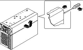
Remove the plastic outer panel that partially covers the top of the chassis:
Only the top portion of the panel must be removed.
-
Using a flat-blade screwdriver as a lever, carefully flex the panel as shown below to disengage it from the chassis.
-
Slide the panel toward the rear of the system until the hooks beneath the panel are disengaged from the chassis.
-
Pull the bottom center edge of the panel outward until it disengages from the chassis.
Lift the panel off the system and set it aside.
Figure 8-14
-
-
Carefully lower the chassis onto its closed side.
Enlist the help of another person to accomplish this safely.
Do not lift the chassis using the plastic panels at the front or the side of the chassis.
Roll the system onto a solid surface that spaces the unit about 2 inches (5 cm) off the floor; for example, use a pair of wooden boards. Do not allow any of the weight to rest on the plastic panels at the front of the chassis.
-
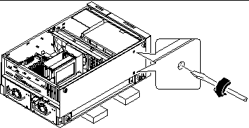
From the underside of the chassis, use a large flat-blade screwdriver to loosen the two captive screws that secure the disk cage to the bottom of the chassis.
Figure 8-15
-
Stand the chassis upright.
Enlist the help of another person to accomplish this safely.
-
From the top of the chassis, use a long flat-blade screwdriver to loosen the two captive screws that secure the disk cage to the upper part of the chassis.
Insert the screwdriver through the two access holes on top of the chassis.
 Caution -
 Take care to avoid damaging any cables that may be located near the captive screws.
-
Remove the disk cage assembly through the open side of the chassis.
Place the assembly on an antistatic mat.
What Next
To replace the disk cage assembly, complete this task:
How to Install the Disk Cage Assembly
What to Do
-
Lift the disk cage assembly into the side of the chassis.
Orient the disk cage so that the open drive bays are facing the front of the chassis. Grasp the free end of the LED ribbon cable (from the LED/keyswitch assembly) and pull it out the front of the disk bay opening to make room for the disk cage.
-
Align the screw holes on top of the cage with the captive screws in the upper part of the chassis.
-
From the top of the chassis, use a long flat-blade screwdriver to partially tighten the two captive screws that secure the disk cage to the chassis.
Insert the screwdriver through the two access holes on top of the chassis to tighten the screws. Before tightening the screws fully, ensure that the two bottom screws are fully tightened (see Step 5). Finish tightening the top two screws only after the bottom screws are tightened.
 Caution -
 Take care to avoid damaging any cables that may be located near the captive screws.
-
Carefully lower the chassis onto its closed side.
Enlist the help of another person to accomplish this safely.
Do not lift the chassis using the plastic panels at the front or the side of the chassis.
Roll the system onto a solid surface that spaces the unit about 2 inches (5 cm) off the floor; for example, use a pair of wooden boards. Do not allow any of the weight to rest on the plastic panels at the front of the chassis.
-
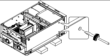
From the underside of the chassis, use a large flat-blade screwdriver to tighten the two captive screws that secure the disk cage to the bottom of the chassis.
Figure 8-16
-
Stand the whole chassis upright.
Enlist the help of another person to accomplish this safely.
-
Finish tightening the two captive screws at the top of the disk cage.
-
Grasp the corner of the LED ribbon cable (hanging in front of the disk bay opening), and fold the cable under itself, so that the label at the end is facing up.
-
Feed the end back into the disk bay opening and route it on top of the disk cage toward the upper-left corner of the UltraSCSI backplane.
Arrange the middle portion of the cable so that it lies flat across the top of the disk cage at the front of the chassis.
-
Reconnect the LED ribbon cable to connector J0602 at the front of the UltraSCSI backplane.
This connector is located in the upper-left corner of the backplane (as viewed from the front). Make sure that the label at the end of the cable faces up. Press down the connector collar to secure the connection.
-
Reconnect the remaining cables to the rear of the UltraSCSI backplane:
-
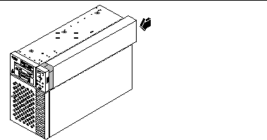
Replace the plastic outer panel that partially covers the top of the chassis:
-
Insert the hooks on the underside of the panel into the corresponding slots in the chassis.
-
Slide the panel toward the front of the system until the hooks engage the chassis, and the rear edge of the panel snaps into place.
Press along the bottom edge of the panel to guide it into place.
-
Figure 8-18
What Next
To reassemble the system, complete these tasks:
Note -
When you reinstall the disk drives, it is important to return each drive to its original location.
How to Remove the Floor Casters Assembly
Before You Begin
Complete this task:
What to Do
-
Carefully turn the system chassis upside down.
Enlist the help of another person to accomplish this safely.
Do not lift the chassis using the plastic panels at the front or the side of the chassis. Place the system onto a solid surface that spaces the unit about 2 inches (5 cm) off the floor; for example, use a pair of wooden boards. Do not allow any of the weight to rest on the plastic panels at the front of the chassis.
-
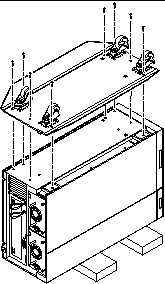
Remove the eight Phillips screws that secure the floor casters assembly to the underside of the chassis.
-
Remove the casters assembly and set it aside.
Note -There are two foot glide mounting brackets attached to the underside of the chassis. Do not remove these brackets unless you are converting the chassis to a rackmount configuration.
Figure 8-19
What Next
To replace the floor casters assembly with foot glides, complete this task:
How to Install the Floor Casters Assembly
Before You Begin
Complete these tasks:
What to Do
-
Carefully turn the system chassis upside down.
Enlist the help of another person to accomplish this safely.
Do not lift the chassis using the plastic panels at the front or the side of the chassis. Place the system onto a solid surface that spaces the unit about 2 inches (5 cm) off the floor; for example, use a pair of wooden boards. Do not allow any of the weight to rest on the plastic panels at the front of the chassis.
Note -The right side of the casters assembly mounts to the two foot glide mounting brackets on the underside of the chassis. If you removed these brackets previously, you must reinstall them now. See "How to Install the Chassis Foot Glides".
-
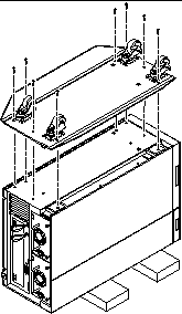
Align the holes in the floor casters assembly with the corresponding mounting holes on the underside of the chassis.
Position the casters assembly with the four casters facing up. Align the two large holes in the assembly with the large holes in the chassis bottom.
Figure 8-20
-
Secure the casters assembly to the chassis using the eight Phillips screws provided with the assembly.
-
Carefully return the chassis to its upright position.
Enlist the help of another person to accomplish this safely. Do not lift the chassis using the plastic panels at the front or the side of the chassis.
How to Remove the Chassis Foot Glides
Before You Begin
Complete this task:
What to Do
-
Carefully turn the system chassis upside down.
Enlist the help of another person to accomplish this safely.
Do not lift the chassis using the plastic panels at the front or the side of the chassis. Place the system onto a solid surface that spaces the unit about 2 inches (5 cm) off the floor; for example, use a pair of wooden boards. Do not allow any of the weight to rest on the plastic panels at the front of the chassis.
-
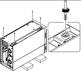
Remove the four plastic foot glides from the underside of the chassis.
Remove the Phillips screw at the center of each foot glide.
Note -Do not remove the two foot glide mounting brackets unless you are converting the chassis to a rackmount configuration.
Figure 8-21
What Next
To replace the foot glides with the optional floor casters assembly, complete this task:
How to Install the Chassis Foot Glides
Before You Begin
Complete this task:
What to Do
-
Carefully turn the system chassis upside down.
Enlist the help of another person to accomplish this safely.
Do not lift the chassis using the plastic panels at the front or the side of the chassis. Place the system onto a solid surface that spaces the unit about 2 inches (5 cm) off the floor; for example, use a pair of wooden boards. Do not allow any of the weight to rest on the plastic panels at the front of the chassis.
-
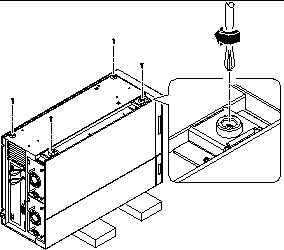
Attach the four plastic foot glides to the corresponding mounting holes on the underside of the chassis.
Insert a Phillips screw through the center of each foot glide.
Note -Two of the plastic foot glides attach directly to the chassis. The other two glides are attached using mounting brackets. These brackets should already be installed on your system. If they are missing, install the two mounting brackets provided with the foot glides. Use two Phillips screws to attach each bracket.
Figure 8-22
-
Carefully return the chassis to its upright position.
Enlist the help of another person to accomplish this safely. Do not lift the chassis using the plastic panels at the front or the side of the chassis.
- © 2010, Oracle Corporation and/or its affiliates

