Chapter 9 Removing and Installing Backplanes and Cables
This chapter describes how to remove and install system backplanes and cables. For a list of part numbers for field-replaceable units and optional equipment, see "Illustrated Parts Breakdown".
Tasks covered in this chapter include:
How to Remove the UltraSCSI Backplane
Before You Begin
Complete these tasks:
Note -
You must remove all disk drives from the disk cage assembly. Be sure to note the disk slot number associated with each drive. Later, when you reinstall the disk drives, it is important to return each drive to its original location.
What to Do
-
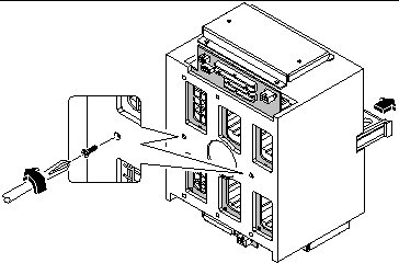
Remove the two screws that secure the cage center divider to the disk cage.
Orient the cage so that the back is facing you. Remove the two screws that are located in the middle of the back.
-
From the front of the disk cage, slide the center divider half way out of the cage.
Figure 9-1
-
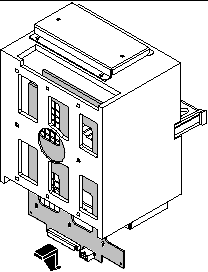
Free the backplane from the six posts that support it at the rear of the disk cage.
Push down on the top edge of the backplane and pull it away from the posts.
-
Slide the backplane out of the opening at the base of the disk cage.
Place the backplane on an antistatic mat.
Figure 9-2
What Next
To replace the UltraSCSI backplane, complete this task:
How to Install the UltraSCSI Backplane
What to Do
-
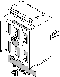
Slide the UltraSCSI backplane into the backplane slot in the base of the disk cage assembly.
Orient the backplane so that the six SCSI drive connectors are facing the open drive bays.
-
Insert the six posts at the rear of the disk cage into the corresponding keyholes in the backplane. Lift the backplane slightly so that each post rests in the narrow part of a keyhole.
Figure 9-3
-
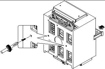
Push the cage center divider back into the disk cage as far as it can go.
The center divider should engage the two large holes in the center of the backplane.
-
Replace the two screws that secure the cage center divider and the backplane to the disk cage assembly.
Figure 9-4
What Next
To reassemble the system, complete these tasks:
Note -
When you reinstall the disk drives, it is important to return each drive to its original location.
How to Remove the Power Distribution Board
Before You Begin
Complete these tasks:
If your system has two power supplies, remove both of them.
What to Do
-
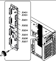
Disconnect all cables attached to the power distribution board.
Start at the top of the board and work your way down.
-
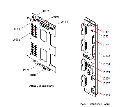
Disconnect the keyswitch/LED cable at connector J0401.
-
Disconnect the system interlock cable at connector J0501.
-
Disconnect the two power sense cables at connectors J0201 and J0202.
-
Disconnect the DC power cables at connectors J0204, J0205, and J0206.
-
Disconnect the UltraSCSI power cable at connector J0207.
-
-
Loosen the two captive Phillips screws that secure the board to its mounting brackets.
One screw is located at the top edge, and the other is located at the bottom edge of the power distribution board.
Figure 9-5
-
Remove the board from the chassis, and place it on an antistatic mat.
What Next
To replace the power distribution board, complete this task:
How to Install the Power Distribution Board
What to Do
-
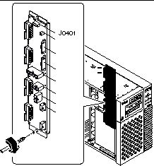
Position the power distribution board in its mounting brackets on the chassis ceiling and floor.
Align the two captive screws at the top and bottom edges of the board with the two holes in the mounting brackets. The four large power connectors along the edge of the board should face the power supply bays.
-
Tighten the two captive Phillips screws that secure the board to its mounting brackets.
It helps to separate the board slightly from its mounting brackets in order to engage the screws in the screw holes.
Figure 9-6
-
Reconnect all cables that you previously detached from the power distribution board.
Start at the top of the board and work your way down.
What Next
To reassemble the system, complete these tasks:
When you are ready to restart the system, be sure to run POST and OpenBoot Diagnostic tests to verify that the system functions correctly with the new parts you have just installed. For additional information, see Chapter 12, Diagnostics and Troubleshooting.
How to Connect the System Cables
Before You Begin
Complete these tasks:
What to Do
-
Identify the cable you wish to install or replace. Use the information in the following tables and illustrations to determine where to connect each end of the cable.
Each cable connector is keyed so that it can be connected in only one way.
-
Install the cable according to the routing and cable management instructions provided in the table.
Note -Part numbers listed in this section are correct as of the manual publication date but are subject to change without notice. Consult your authorized Sun sales representative or service provider to confirm a part number prior to ordering a replacement part.
Table 9-1Cable Name
Connections
Routing and Management
CPU 3.3V Power Cable
From: Power Distribution Board
(J0205, J0206)
To: Main Logic Board (J2903)
Tie-wrapped with other cables to chassis ceiling in two locations near fan tray assembly.
CPU 5V/Core Voltage Power Cable
From: Power Distribution Board (J0204)
To: Main Logic Board (J2902)
Tie-wrapped with other cables to chassis ceiling in two locations near fan tray assembly.
System Interlock Cable
From: Power Distribution Board (J0501)
To: Chassis rear wall
To: Chassis front wall near removable media assembly
Tie-wrapped with other cables to chassis ceiling in two locations near fan tray assembly. Tie-wrapped alone to chassis ceiling and rear wall in four more locations. Switch at one end of cable is attached to rear chassis wall with two small Phillips screws. Switch at front end of cable is attached to the front chassis wall with two small Phillips screws.
14-pin Power Sense/I2C Cable
From: Power Distribution Board (J0202)
To: Main Logic Board (J4501)
Tie-wrapped with other cables to chassis ceiling in two locations near fan tray assembly.
16-pin Power Sense/Control Cable
From: Power Distribution Board (J0201)
To: Main Logic Board (J2901)
Tie-wrapped with other cables to chassis ceiling in two locations near fan tray assembly.
UltraSCSI Power Cable
From: Power Distribution Board (J0207)
To: UltraSCSI Backplane (J0101)
Routed behind fan tray assembly.
UltraSCSI Data Cable
From: Main Logic Board (J1801)
To: UltraSCSI Backplane (J0102)
Routed behind fan tray assembly.
Keyswitch/LED Cable
From: Power Distribution Board (J0401)
To: UltraSCSI Backplane (J0103)
Routed behind fan tray assembly.
Removable Media SCSI Cable
From: UltraSCSI Backplane (J0501)
To: CD-ROM/Tape Drive SCSI
Connector
Includes connectors for two RMA SCSI devices.
Removable Media Power Cable
From: UltraSCSI Backplane (J0104)
To: CD-ROM/Tape/Diskette Drive
Power Connectors
Includes connectors for two RMA SCSI devices and one optional diskette drive.
Diskette Data Cable
From: UltraSCSI Backplane (J0502)
To: Diskette Drive Data Connector
Fan Tray Cable
From: Power Distribution Board (J0303)
To: Fan Tray Connector
Cable end labeled P1 connects to power distribution board.
Figure 9-7
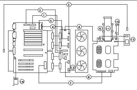 Table 9-2
 Key
Description
Key
Part Number
1
CPU 3.3V Power Cable -- 530-2444
8
Keyswitch/LED Cable -- 530-2525
2
CPU 5V/Core Voltage Power Cable -- 530-2441
9
Removable Media SCSI Cable -- 530-2445
3
System Interlock Cable -- 530-2482
10
Removable Media Power Cable -- 530-2440
4
14-pin Power Sense/I2C Cable -- 530-2480
11
Diskette Data Cable -- 530-2439
5
16-pin Power Sense/Control Cable -- 530-2481
12
Fan Tray Cable -- 530-2685
6
UltraSCSI Power Cable -- 530-2443
13
LED/Keyswitch Assembly [To install this part, see "How to Install the LED/Keyswitch Assembly".] -- 540-3604
7
UltraSCSI Data Cable -- 530-2446
14
SSP Paddle Card and Cable [To install this part, see "How to Install the SSP Paddle Card".] -- 501-4818
Figure 9-8
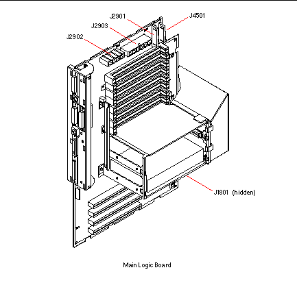
Figure 9-9
What Next
To reassemble the system, complete these tasks:
- © 2010, Oracle Corporation and/or its affiliates
