Chapter 10 Administration and Networking
This chapter focuses on administrative tasks associated with Ethernet interfaces and the disk array.
Tasks covered in this chapter include:
Other information covered in this chapter includes:
About Network Interface Options
The system's main logic board provides an auto-sensing, switchable 10BASE-T/100BASE-TX Ethernet interface conforming to the IEEE 802.3u Ethernet standard. The interface configures itself automatically for either 10-Mbps or 100-Mbps operation, depending on network characteristics.
Two rear panel connectors provide access to the Ethernet interface:
-
One RJ-45 connector for connecting a twisted-pair Ethernet (TPE) cable
-
One Media Independent Interface (MII) connector for connecting an external MII transceiver
Note -
You can use only one of the main logic board Ethernet connectors; you cannot connect to the TPE and MII connectors at the same time.
The Media Independent Interface lets you connect the system to a variety of external Ethernet transceivers, providing compatibility with different Ethernet wiring types. When an external transceiver is connected to the MII, the system automatically activates the MII port and disables the TPE port.
Sun Microsystems offers an MII-to-AUI transceiver as a separately orderable option (order number X467A). A number of third-party MII transceivers are also available for connecting to TX, T4, FX, and AUI-type Ethernet networks.
For instructions on configuring the main logic board Ethernet interface, see "How to Configure the Standard Ethernet Interface". For information about operating characteristics and configuration parameters for the hme Fast Ethernet device driver, please see Platform Notes: The Fast Ethernet Device Driver. This document is available on Solaris on Sun Hardware AnswerBook, which is provided on the SMCC Supplement CD for the Solaris release you are running.
Additional network interfaces are available through PCI cards, providing connection to Ethernet, token ring, FDDI, and other network types. For more information, see "How to Add an Ethernet Interface" and the documentation supplied with the PCI network interface card.
How to Configure the Standard Ethernet Interface
Before You Begin
You must perform the following tasks:
-
Complete the prerequisite steps in "How to Install the Enterprise 250 Server".
-
Determine which of the two Ethernet ports you want to use; see "About Network Interface Options".
-
Attach a cable to the appropriate Ethernet port; see "How to Attach a Twisted-Pair Ethernet (TPE) Cable" or "How to Attach an MII Ethernet Transceiver".
Note -
You can configure only one Ethernet interface during installation of the operating system. To configure additional interfaces, see "How to Add an Ethernet Interface".
What to Do
-
Assign a host name to the machine.
The host name must be unique within the network. It can be made up of characters and numbers. Do not use a dot in the host name. Do not begin the name with a number or a special character.
-
Determine the IP address for the interface.
Your network administrator must assign an IP address. Each network device or interface must have a unique IP address.
-
Resume the installation of the system.
See "How to Install the Enterprise 250 Server". When installing the operating system, you may be prompted to enter the host name and IP address of the machine.
Note -If you have installed a PCI card as a second Ethernet interface, the operating system asks you to select a primary network interface and then prompts you for its host name and IP address. You must configure the second interface separately, after the operating system is installed. See "How to Add an Ethernet Interface".
Note -This system conforms to the Ethernet 10/100BASE-T standard, which states that the Ethernet 10BASE-T link integrity test function should always be enabled on both the host system and the Ethernet hub. If you have problems verifying connection between this system and your hub, verify that the Ethernet hub also has the link test function enabled. See "Network Communications Failure" and refer to the manual provided with your hub for more information about the link integrity test function.
What Next
After completing this procedure, the Ethernet interface is ready for operation. However, in order for other network devices to communicate with the system, your network administrator must enter the system's IP address and host name into the namespace on the network name server. For information about setting up a network name service, consult the Solaris System Administrator AnswerBook for your specific Solaris release.
The hme Fast Ethernet device driver for the system's standard Ethernet interface is automatically installed with the Solaris release. For information about operating characteristics and configuration parameters for the hme driver, please see Platform Notes: The hme Fast Ethernet Device Driver. This document is available on Solaris on Sun Hardware AnswerBook, which is provided on the SMCC Supplement CD for the Solaris release you are running.
If you want to install an additional network interface by means of a PCI card, you must configure it separately, after installing the operating system; see:
How to Add an Ethernet Interface
Before You Begin
Follow this procedure to add a PCI card that provides an additional Ethernet interface.
You must perform the following tasks:
-
Install the system; see "How to Install the Enterprise 250 Server".
-
Install any additional PCI Ethernet interface cards that you wish to configure; see "How to Install a PCI Card".
-
Attach a cable to the new Ethernet port and to the network; see "How to Attach a Twisted-Pair Ethernet (TPE) Cable" or "How to Attach an MII Ethernet Transceiver".
What to Do
-
Assign a network host name to the interface.
The host name must be unique within the network. It can be made up of characters and numbers. Do not use a dot in the host name. Do not begin the name with a number or a special character.
Usually an interface host name is based on the machine host name. For example, if the machine is assigned the host name zardoz, then the additional Ethernet interface could be named zardoz-1. The machine's host name is assigned when the operating system software is installed. For more information, see the installation instructions accompanying the Solaris software.
-
Determine the IP address for the interface.
An IP address must be assigned by your network administrator. Each interface on a network must have a unique IP address.
-
Boot the operating system and log on to the system as superuser.
Enter the following command at the system prompt, and the superuser password:
zardoz # su
Password:
-
Create an appropriate /etc/hostname file for the new interface.
The name of the file you create should be of the form /etc/hostname.typenum, where type is the Ethernet type identifier (some common types are hme, le, nf, and ie) and num is the logical number of the interface according to the order in which it was installed in the system.
For example, the standard interface provided on the system's main logic board is hme0 (type = hme, num = 0). If you add a SunSwift(TM) PCI Ethernet adapter card as a second hme interface, the file name should be hostname.hme1.
Note -The documentation accompanying the Ethernet interface should identify its type. Alternatively, you can enter the show-devs command from the ok prompt to obtain a list of all installed devices.
The host name has an associated IP address that you enter in the /etc/hosts file. See Step 6.
-
Enter the host name, assigned in Step 1, to the /etc/hostname file for the new interface.
Following is an example of the /etc/hostname files required for a machine called zardoz, which has two Ethernet interfaces--the standard on-board Ethernet interface (hme0) and a second interface provided by a PCI Ethernet adapter card (hme1). The host name will be zardoz to a network connected to the standard hme0 interface, and zardoz-1 to a network connected to the hme1 interface.
zardoz # cat /etc/hostname.hme0
zardoz
zardoz # cat /etc/hostname.hme1
zardoz-1
-
Create an entry in the /etc/hosts file for each active Ethernet interface.
An entry consists of the IP address and the host name for each interface.
The following example shows the entries in the /etc/hosts file for the interfaces identified in the /etc/hostname file created in Step 4 and Step 5.
zardoz # cat /etc/hosts
...
127.0.0.1     localhost
129.144.10.57 zardoz    loghost
129.144.11.83 zardoz-1
-
zardoz # reboot -- -r
This command rebuilds the device trees so that the system will recognize the newly installed PCI Ethernet adapter card.
What Next
After completing this procedure, the Ethernet interface is ready for operation. However, in order for other network devices to communicate with the system through this interface, the interface information (its IP address and host name) must be entered into the namespace on the network name server. For information about setting up a network name service, consult the Solaris System Administrator AnswerBook for your specific Solaris release.
How to Attach a Twisted-Pair Ethernet (TPE) Cable
Before You Begin
If you are attaching a twisted-pair Ethernet (TPE) cable to the system's standard Ethernet interface, you must perform the following task:
-
Complete prerequisite steps in "How to Install the Enterprise 250 Server".
If you are installing an additional Ethernet interface, you must perform the following tasks:
-
Install the system; see "How to Install the Enterprise 250 Server".
-
Install a PCI Ethernet interface card; see "How to Install a PCI Card".
What to Do
-
Locate the RJ-45 connector for the appropriate Ethernet interface.
The system comes with one TPE connector on the rear panel. Your system may also include one or more additional TPE connectors provided via PCI Ethernet interface cards.
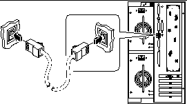
-
Plug in the TPE cable to the appropriate RJ-45 connector.
You should hear the connector tab snap into place.
Figure 10-1

-
Plug in the other end of the cable to the TPE outlet in the wall or the floor.
You should hear the connector tab snap into place.
See your network administrator if you need more information about how to connect to your network.
Note -You can use only one of the main logic board Ethernet ports. You cannot connect to the main logic board's TPE and MII ports at the same time. For information about connecting to the MII port, see "How to Attach an MII Ethernet Transceiver".
What Next
If you are installing your system, complete the installation procedure. Return to:
If you are adding additional interfaces to the system, then you need to configure those interfaces; see:
How to Attach an MII Ethernet Transceiver
The Media Independent Interface (MII) lets you connect the system to a variety of external Ethernet transceivers, providing compatibility with different Ethernet wiring types.
You can order an MII-to-AUI transceiver from Sun Microsystems as a separate option (order number X467A). A number of third-party MII transceivers are also available for connecting to TX, T4, FX, and AUI-type Ethernet networks.
The procedure below assumes you are connecting the Sun MII-to-AUI transceiver. For third-party transceivers, see the documentation supplied with the transceiver.
Before You Begin
If you are attaching an Ethernet Media Independent Interface (MII) transceiver to the system's standard Ethernet interface, you must have already performed the following task:
-
Completed prerequisite steps in "How to Install the Enterprise 250 Server"
If you are adding an Ethernet interface, you must have already performed the following tasks:
-
Installed the system; see "How to Install the Enterprise 250 Server"
-
Installed a PCI Ethernet interface card; see "How to Install a PCI Card"
What to Do
-
Locate the appropriate MII Ethernet connector.
The system comes with one MII Ethernet connector on the rear panel. Your system may also include one or more additional TPE connectors provided via PCI Ethernet interface cards.
-
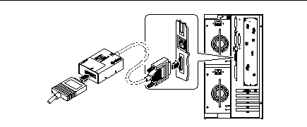
Plug the MII Ethernet transceiver into the MII Ethernet connector on the system rear panel.
Figure 10-2

-
Attach the network AUI cable to the AUI connector on the MII-to-AUI transceiver.
-
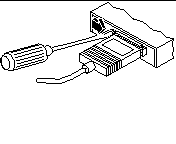
Lock the AUI connector.
As viewed from the top, slide the latch to the right to lock the AUI cable to the MII-to-AUI transceiver. Use a flat-blade screwdriver, if necessary.
Figure 10-3

-
Connect the other end of the cable to the appropriate network device.
There are a variety of connector and cabling options available for the AUI connection. See your network administrator if you need more information about how to connect to your network.
Note -You can use only one of the main logic board Ethernet ports. You cannot connect to the main logic board's TPE and MII ports at the same time. For information about connecting to the TPE port, see "How to Attach a Twisted-Pair Ethernet (TPE) Cable".
What Next
If you are installing your system, then complete the installation procedure. Return to:
If you are adding an additional interface to your system, then you need to configure that interface; see:
How to Boot the System Using the Standard Ethernet Interface
Before You Begin
Before you can boot the system over a network interface, you must complete the installation procedure; see:
Specifically, you must perform the following tasks:
-
Set up a system console; see "About Setting Up a Console"
-
Configure the Ethernet port; see "How to Configure the Standard Ethernet Interface"
-
Attach the Ethernet port to a network; see "How to Attach a Twisted-Pair Ethernet (TPE) Cable" or "How to Attach an MII Ethernet Transceiver"
-
Power on the system; see "How to Power On the System"
Note -
To boot the system over an Ethernet network, it is necessary that there be a bootable image for Sun4u architecture somewhere on the network. For details, see the installation instructions accompanying your Solaris software.
What to Do
-
At the ok prompt, enter either of the following commands:
-
To load the operating system into the server's volatile memory, enter:
ok boot net
Note -Because the operating system is only in volatile memory, it is not retained across power cycles.
-
To install the operating system onto the server's internal system disk, enter:
ok boot net - install
Both commands boot the system, and the system console displays the system prompt.
-
What Next
If you want to use the main logic board Ethernet interface as the default boot device, you must change the value of certain OpenBoot parameters. For more information, see OpenBoot 3.x Command Reference Manual in the Solaris System Administrator AnswerBook for your specific Solaris release.
How to Boot the System Using a PCI-Based Ethernet Interface
Before You Begin
Before you can boot the system over a network interface, you must complete the installation procedure; see:
Specifically, you must perform the following tasks:
-
Set up a system console; see "About Setting Up a Console"
-
Configure the PCI-based Ethernet port; see "How to Add an Ethernet Interface"
-
Attach the Ethernet port to a network; see "How to Attach a Twisted-Pair Ethernet (TPE) Cable" or "How to Attach an MII Ethernet Transceiver"
-
Power on the system; see "How to Power On the System"
Note -
To boot the system over an Ethernet network, it is necessary that there be a bootable image for Sun4u architecture somewhere on the network. For details, see the installation instructions accompanying your Solaris software.
What to Do
-
ok show-devs
The show-devs command lists the system devices. It displays the full path name of the hme device, similar to the example below:
/pci@1f,4000/pci@5/SUNW,hme@0,1
-
Change the default net device. At the ok prompt, enter:
ok nvalias net
hme_path
ok nvstore
where hme_path is the full path name of the hme device--in this example, /pci@1f,4000/pci@5/SUNW,hme@0,1.
-
Load and boot the operating system over the network interface. Enter either of the following commands:
-
To load the operating system into the server's volatile memory, enter:
ok boot net
Note -Because the operating system is only in volatile memory, it is not retained across power cycles.
-
To install the operating system onto the server's internal system hard drive, enter:
ok boot net - install
Both commands boot the system, and the system console displays the system prompt.
-
What Next
If you want to use this Ethernet interface as the default boot device, you must permanently change the value of the boot-device parameter. For more information, see:
-
OpenBoot 3.x Command Reference Manual in the Solaris System Administrator AnswerBook for your specific Solaris release
How to Select the Boot Device
Before You Begin
Before you can select a boot device, you must complete the installation procedure; see:
Specifically, you must perform the following tasks:
-
Set up a system console; see "About Setting Up a Console"
-
Power on the system; see "How to Power On the System"
If you want to boot across a network interface, then you must also perform the following tasks:
-
Configure the Ethernet port; see "How to Configure the Standard Ethernet Interface"
-
Attach the Ethernet port to a network; see "How to Attach a Twisted-Pair Ethernet (TPE) Cable" or "How to Attach an MII Ethernet Transceiver"
The device that is used to boot the system is determined by the setting of an OpenBoot firmware configuration parameter called boot-device. The default setting of this parameter is disk net. Because of this setting, the firmware first attempts to boot from the system hard drive, and if that fails, then from the main logic board Ethernet interface.
This procedure assumes that you are familiar with the OpenBoot firmware and that you know how to enter the OpenBoot environment. For more information about the OpenBoot firmware, see OpenBoot 3.x Command Reference Manual in the Solaris System Administrator AnswerBook for your specific Solaris release.
What to Do
-
ok setenv boot-device
device-specifier
where the device-specifier is one of the following:
-
cdrom - Selects the CD-ROM drive
-
disk - Selects the hard disk
-
floppy - Selects the 3.5-inch diskette drive
-
tape - Selects the SCSI tape drive
-
net - Selects the Ethernet interface on the main logic board
-
full path name - Selects the Ethernet interface specified by the path name
Note -You can also specify the name of the program to be booted as well as the way the boot program operates. For more information, see OpenBoot 3.x Command Reference Manual in the Solaris System Administrator AnswerBook for your specific Solaris release.
If you want to select a network interface other than the system board Ethernet interface as the default boot device, you can determine the full path name of each interface, by entering:
ok show-devs
The show-devs command lists the system devices. It displays the full path name of each PCI device. An example of a path name is shown below:
/pci@1f,4000/pci@5/SUNW,hme@0,1
-
-
To reboot the system from the new boot device, enter:
ok reset
Note -You can also power cycle the system using the front panel keyswitch.
What Next
For more information about using the OpenBoot firmware, see OpenBoot 3.x Command Reference Manual in the Solaris System Administrator AnswerBook for your specific Solaris release.
About Disk Array Configurations and Concepts
The Solstice DiskSuite software designed for use with the system lets you configure the machine's internal disks in several configurations called disk arrays, which improve performance, capacity, and availability.
Note -
Solstice DiskSuite and other software must be ordered separately.
This section describes some of the most popular and useful of those configurations, including:
-
Disk concatenation
-
Disk mirroring (RAID 1)
-
Disk striping (RAID 0)
-
Disk striping with parity (RAID 5)
-
Hot spares
-
Hot plug
The DiskSuite software creates metadevices--logical disk devices consisting of one or more physical disks or partitions from several disks. Once you use Solstice DiskSuite to create a metadevice, the operating system uses and maintains the metadevice as if it were a single device.
For instance, you can combine the three disks c1t2d0s2, c1t3d0s2, and c1t4d0s2 into the metadevice /dev/md/rdsk/d0.
Disk Concatenation
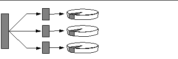
Disk concatenation is a method for increasing logical volume size beyond the capacity of one disk drive by creating one large metadevice from two or more smaller drives. This lets you create arbitrarily large partitions.
Figure 10-4

Using this method, the concatenated disks are filled with data sequentially, with the second disk being written to when no space remains on the first, the third when no room remains on the second, and so on.
RAID 1: Disk Mirroring
Disk mirroring is a technique that uses data redundancy--two complete copies of all data stored on two separate disks--to protect against loss of data due to disk failure. One metadevice is created from two disks.
Figure 10-5

Whenever the operating system needs to write to the mirrored metadevice, both disks are updated. The disks are maintained at all times with exactly the same information. When the operating system needs to read from the mirrored metadevice, it reads from whichever disk is more readily accessible at the moment. The scheme is sometimes called RAID 1, where RAID stands for Redundant Arrays of Inexpensive Disks.
RAID 1 offers the highest level of data protection, but storage costs are high, since all data is stored twice.
RAID 0: Disk Striping
Disk striping (sometimes called RAID 0) is a technique for increasing system throughput by using several disk drives in parallel. Whereas in non-striped disks the operating system writes a single block to a single disk, in a striped arrangement each block is divided and portions of the data are written to different disks.
Figure 10-6

System performance using RAID 0 will be better than using RAID 1 or 5, but the possibility of data loss is greater because there is no way to retrieve or reconstruct data stored on a failed drive.
RAID 5: Disk Striping With Parity
RAID Level 5 is an implementation of disk striping in which parity information is included with each disk write. The advantage of the technique is that if any one disk in a RAID 5 array fails, all the information on the failed drive can be reconstructed from the data and parity on the remaining disks.
System performance using RAID 5 will fall between that of RAID 0 and RAID 1, and all data loss is fully protected.
Hot Spares
In a "hot spares" arrangement, one or more disk drives are installed in the system but are unused during normal operation. Should one of the active drives fail, disk write operations are automatically redirected to a hot spare disk and the failed disk drive is retired from operation.
Hot Plug
The system's disk bays are designed to permit disk drive removal and insertion while the system is powered on. Hot-plug technology significantly increases the system's serviceability and availability, by providing the ability to:
-
Add additional hardware dynamically to enable the system to handle an increasingly larger work load, perform load balancing, and improve performance of a running system.
-
Remove/replace faulty hardware with minimal system service disruption.
For more information about hot-pluggable disk drives, see "About Internal Disk Drives".
For More Information
See the documentation supplied with the Solstice DiskSuite software.
- © 2010, Oracle Corporation and/or its affiliates
