How to Connect the System Cables
Before You Begin
Complete these tasks:
What to Do
-
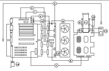
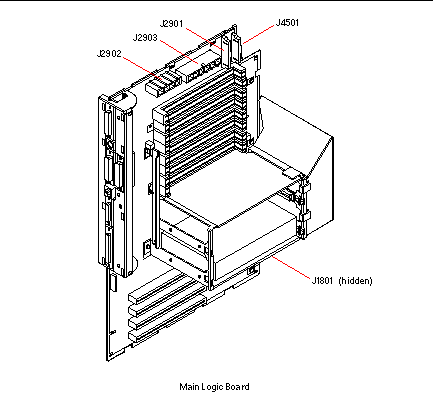
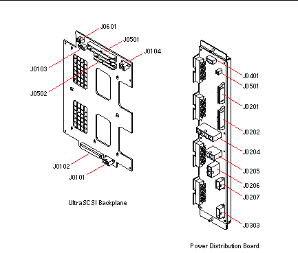
Identify the cable you wish to install or replace. Use the information in the following tables and illustrations to determine where to connect each end of the cable.
Each cable connector is keyed so that it can be connected in only one way.
-
Install the cable according to the routing and cable management instructions provided in the table.
Note -Part numbers listed in this section are correct as of the manual publication date but are subject to change without notice. Consult your authorized Sun sales representative or service provider to confirm a part number prior to ordering a replacement part.
Table 9-1Cable Name
Connections
Routing and Management
CPU 3.3V Power Cable
From: Power Distribution Board
(J0205, J0206)
To: Main Logic Board (J2903)
Tie-wrapped with other cables to chassis ceiling in two locations near fan tray assembly.
CPU 5V/Core Voltage Power Cable
From: Power Distribution Board (J0204)
To: Main Logic Board (J2902)
Tie-wrapped with other cables to chassis ceiling in two locations near fan tray assembly.
System Interlock Cable
From: Power Distribution Board (J0501)
To: Chassis rear wall
To: Chassis front wall near removable media assembly
Tie-wrapped with other cables to chassis ceiling in two locations near fan tray assembly. Tie-wrapped alone to chassis ceiling and rear wall in four more locations. Switch at one end of cable is attached to rear chassis wall with two small Phillips screws. Switch at front end of cable is attached to the front chassis wall with two small Phillips screws.
14-pin Power Sense/I2C Cable
From: Power Distribution Board (J0202)
To: Main Logic Board (J4501)
Tie-wrapped with other cables to chassis ceiling in two locations near fan tray assembly.
16-pin Power Sense/Control Cable
From: Power Distribution Board (J0201)
To: Main Logic Board (J2901)
Tie-wrapped with other cables to chassis ceiling in two locations near fan tray assembly.
UltraSCSI Power Cable
From: Power Distribution Board (J0207)
To: UltraSCSI Backplane (J0101)
Routed behind fan tray assembly.
UltraSCSI Data Cable
From: Main Logic Board (J1801)
To: UltraSCSI Backplane (J0102)
Routed behind fan tray assembly.
Keyswitch/LED Cable
From: Power Distribution Board (J0401)
To: UltraSCSI Backplane (J0103)
Routed behind fan tray assembly.
Removable Media SCSI Cable
From: UltraSCSI Backplane (J0501)
To: CD-ROM/Tape Drive SCSI
Connector
Includes connectors for two RMA SCSI devices.
Removable Media Power Cable
From: UltraSCSI Backplane (J0104)
To: CD-ROM/Tape/Diskette Drive
Power Connectors
Includes connectors for two RMA SCSI devices and one optional diskette drive.
Diskette Data Cable
From: UltraSCSI Backplane (J0502)
To: Diskette Drive Data Connector
Fan Tray Cable
From: Power Distribution Board (J0303)
To: Fan Tray Connector
Cable end labeled P1 connects to power distribution board.
Figure 9-7
 Table 9-2
 Key
Description
Key
Part Number
1
CPU 3.3V Power Cable -- 530-2444
8
Keyswitch/LED Cable -- 530-2525
2
CPU 5V/Core Voltage Power Cable -- 530-2441
9
Removable Media SCSI Cable -- 530-2445
3
System Interlock Cable -- 530-2482
10
Removable Media Power Cable -- 530-2440
4
14-pin Power Sense/I2C Cable -- 530-2480
11
Diskette Data Cable -- 530-2439
5
16-pin Power Sense/Control Cable -- 530-2481
12
Fan Tray Cable -- 530-2685
6
UltraSCSI Power Cable -- 530-2443
13
LED/Keyswitch Assembly [To install this part, see "How to Install the LED/Keyswitch Assembly".] -- 540-3604
7
UltraSCSI Data Cable -- 530-2446
14
SSP Paddle Card and Cable [To install this part, see "How to Install the SSP Paddle Card".] -- 501-4818
Figure 9-8

Figure 9-9

What Next
To reassemble the system, complete these tasks:
- © 2010, Oracle Corporation and/or its affiliates
