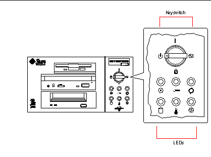
About the Status and Control Panel
The status and control panel includes six LED indicators and a security keyswitch. The panel is located in the top-right corner of the system front panel, as shown in "Locating Front Panel Features".
Figure 1-4

The front panel keyswitch controls the power-on mode of the system. The following table describes the function of each switch setting.
Table 1-1|
Name |
Icon |
Description |
|---|---|---|
|
Power-On |
Turns the system power on. |
|
|
Diagnostics |
Turns the system power on and runs power-on self-test (POST) and OpenBoot(TM) diagnostics (OBDiag).
Turn the switch to this setting when you want to run POST and OBDiag at power-up. For more information on POST and OBDiag, see "About Diagnostic Tools". |
|
|
Locked |
Turns the system power on and disables the keyboard Stop-a command and terminal Break key command. This prevents users from suspending system operation and accessing the system ok prompt in order to modify OpenBoot configuration parameters stored in the system's nonvolatile memory.
This setting also prevents unauthorized programming of the system flash PROM. For additional details, see "About Flash PROM Jumpers".
This is the recommended setting for normal day-to-day operation of the system. |
|
|
Standby |
Places the system in standby mode by turning off power to all internal system components and placing the power supplies in standby mode. When the keyswitch is in this position, the keyboard power switch is disabled. |
The LEDs consist of two types: system health indicators and fault indicators. The system health indicators light to show you that the system is functioning normally. The fault indicators light when a problem is detected in the system. Because it is important for you to know that a fault exists in the system, the fault indicators remain lit when the system is reset or switched to standby mode using the keyswitch.
When you first power on the system, the LEDs are individually toggled on and off to verify that each one is working correctly. After that, the LEDs operate as described in the following table.
Table 1-2|
Name |
Icon |
Description |
|---|---|---|
|
Power-on |
This green LED lights steadily when the system power is on and the keyswitch is in the On, Diagnostics, or Locked position. |
|
|
General fault |
This yellow LED blinks slowly while the system runs its power-on self-test (POST) diagnostics and blinks rapidly during OpenBoot diagnostic (OBDiag) tests. It lights steadily when any fault is detected (including a fault also reported by any other LED). |
|
|
Activity |
This green LED blinks continuously to indicate that the system is operating normally. |
|
|
Disk fault |
This yellow LED lights steadily to indicate a fault in one of the hard disk drives. When this LED is lit, one or more disk LEDs may also be lit, indicating the source of the fault. |
|
|
Temperature fault |
This yellow LED lights steadily to indicate an over-temperature condition in the system. |
|
|
Power supply fault |
This yellow LED lights steadily to indicate a power supply fault. LEDs on the rear of the power supply indicate the nature of the fault (and identify which supply is faulty in a system with two supplies). |
- © 2010, Oracle Corporation and/or its affiliates
