Chapter 2 Photographic Tour of System
System View
Figure 2-1
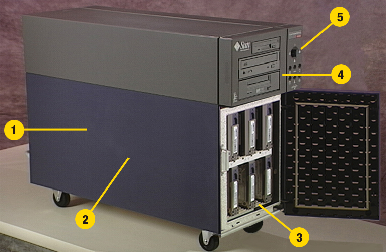
2. "Internal System Components"
4. "Removable Media Components"
For additional information, see:
Internal System Components
Figure 2-2

7. "Main Logic Board Components"
Removable Media Components
Figure 2-3
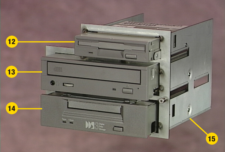
12. "Diskette Drive"
13. "CD-ROM Drive"
14. "Tape Drive"
15. "Removable Media Assembly"
Main Logic Board Components
Figure 2-4
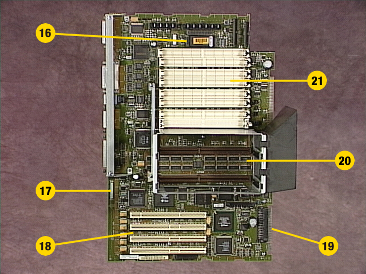
17. "SSP Paddle Card and Cable"
18. "PCI Cards"
20. "CPU Modules"
21. "Memory Modules"
Side Access Panel
Figure 2-5
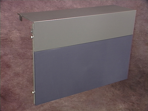
For information related to this part, see:
Disk Drives
Figure 2-6
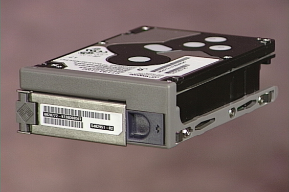
For information related to this part, see:
Removable Media Assembly
Figure 2-7

For information related to this part, see:
Diskette Drive
Figure 2-8

For information related to this part, see:
CD-ROM Drive
Figure 2-9

For information related to this part, see:
Tape Drive
Figure 2-10

For information related to this part, see:
Main Logic Board
Figure 2-11
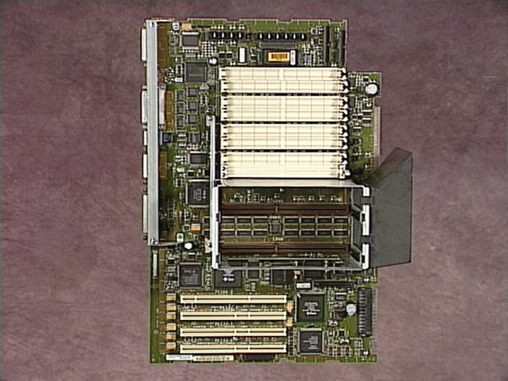
For information related to this part, see:
CPU Modules
Figure 2-12
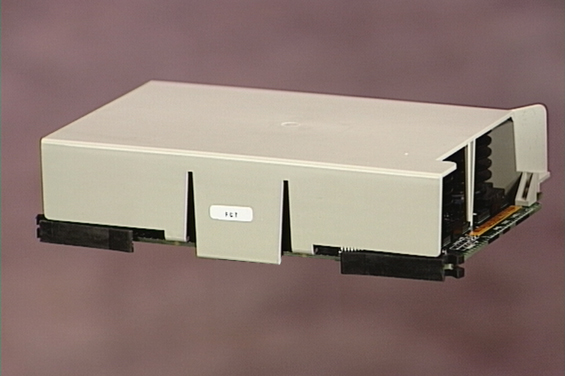
For information related to this part, see:
Memory Modules
Figure 2-13
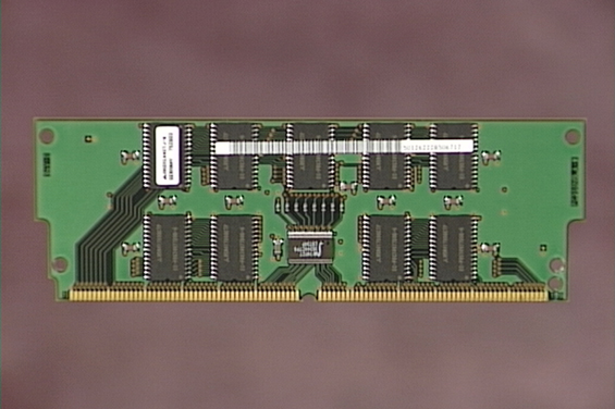
For information related to this part, see:
PCI Cards
Figure 2-14

For information related to this part, see:
SSP Paddle Card and Cable
Figure 2-15

For information related to this part, see:
NVRAM/TOD Module
Figure 2-16

For information related to this part, see:
Power Supply
Figure 2-17
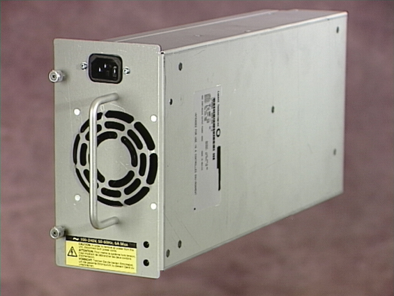
For information related to this part, see:
Power Distribution Board
Figure 2-18
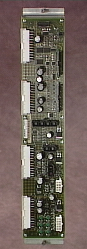
For information related to this part, see:
Disk Cage Assembly
Figure 2-19
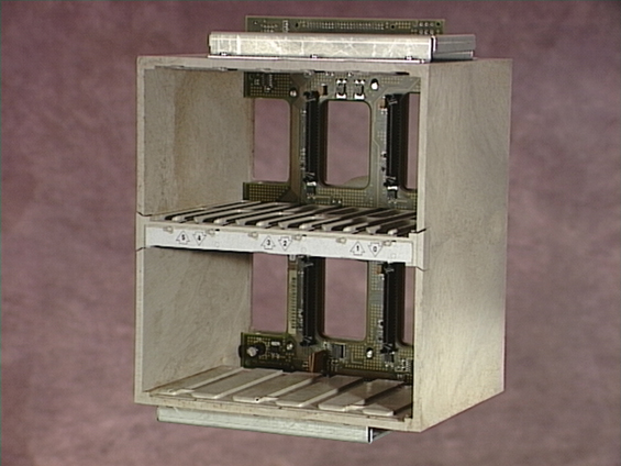
For information related to this part, see:
UltraSCSI Backplane
Figure 2-20
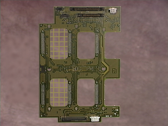
For information related to this part, see:
Fan Tray Assembly
Figure 2-21
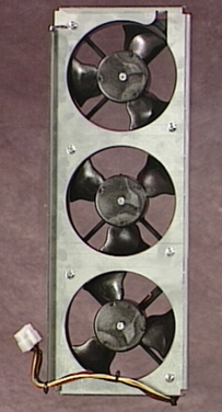
For information related to this part, see:
LED/Keyswitch Assembly
Figure 2-22
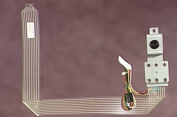
For information related to this part, see:
- © 2010, Oracle Corporation and/or its affiliates
