Chapter 1 System Overview
This chapter introduces you to the Sun Enterprise 250 server and explains some of its features. Information covered in this chapter includes:
About the Sun Enterprise 250 Server
The Sun Enterprise 250 server is a high-performance, shared memory, symmetric-multiprocessing server system. It is designed around Sun's high-speed Ultra Port Architecture (UPA) cross-bar system interconnect and Sun's UltraSPARCTM II processors to deliver outstanding overall system performance.
The system is housed in a roll-around tower enclosure, which measures 20.4 inches high, 10.3 inches wide, and 27.1 inches deep (51.7 cm x 26.2 cm x 68.8 cm). The system has a maximum weight of 118 lb (53 kg).
Processing power is provided by up to two modular UltraSPARC II CPUs, each of which comes with 1 Mbyte or 2 Mbytes of local high-speed external cache memory. The system UPA's clock rate synchronizes automatically to the clock rate of the installed CPUs, and the UPA bus operates at a clock rate that is one third or one fourth that of the CPU modules. For more information about CPU modules, see "About CPU Modules".
System main memory is provided by up to sixteen memory DIMM modules, each of which is capable of storing 32, 64, or 128 Mbytes of data. Total main memory is expandable up to 2 gigabytes. To enhance memory I/O performance, the system transfers 64 bytes of data into or from memory on each memory transfer. For more information about system memory, see "About Memory".
System I/O is handled by two separate Peripheral Component Interconnect (PCI) buses. These industry-standard buses support all main logic board I/O and up to four PCI interface cards. One PCI bus operates at a 33-MHz clock rate and supports up to three PCI cards, while the other bus can operate at either 33-MHz or 66-MHz and supports one PCI card. All PCI cards plug into slots provided on the system's main logic board. For more information about PCI buses, see "About Peripheral Component Interconnect (PCI) Buses".
Internal disk storage is provided by up to six hot-swappable 1-inch or 1.6-inch high, 3.5-inch wide, UltraSCSI disk drives. All six drives are supported by a 40-Mbyte per second UltraSCSI interface provided directly on the system's main logic board. For more information about disk storage, see "About Internal Disk Drives".
External multi-disk storage subsystems and RAID storage arrays can be supported by installing single-channel or multi-channel PCI host adapter cards along with the appropriate system software. Software drivers supporting SCSI and other types of devices are included in the Solaris operating environment.
An internal CD-ROM drive is standard on the Enterprise 250 server. The CD-ROM drive has multimedia features, which include multi-session capability and fast access for image and video data. An optional 1.44-Mbyte, 3.5-inch diskette drive is also available.
A 5.25-inch half-height (1.6-inch) bay is provided at the front of the system, which may be used to house a removable media SCSI device--such as an 8-mm tape drive, a 4-mm DDS-2 or DDS-3 tape drive, or a quarter-inch cassette tape drive. For additional details, see "About the SCSI Removable Media Bays and the External SCSI Port".
Up to four external tape devices can be attached to the standard 68-pin Fast/Wide SCSI port provided on the system's rear panel. Additional external tape devices can be supported with appropriate PCI host adapter cards.
The Enterprise 250 server can easily be connected to either a 10-Mbps or a 100-Mbps Ethernet by means of an auto-sensing Ethernet interface provided on the system's main logic board. Additional Ethernet interfaces or connections to other networks, such as FDDI, ATM, or token ring, can be provided by installing the appropriate PCI interface cards. For more information, see Chapter 10, Administration and Networking.
The system console device can be either a standard ASCII character terminal or a local windowing subsystem. The ASCII terminal connects to the one of the system's two serial ports, while a local graphics console requires installation of a PCI frame buffer card, monitor, keyboard, and mouse. System administration can also be performed from a remote workstation connected to the Ethernet.
The Enterprise 250 server provides two serial communications ports through a pair of DB-25 connectors located on the rear panel. It also provides one external, 2-Mbyte per second, bidirectional, Centronics-compatible, EPP parallel port for connecting the system to a local printer or other compatible parallel device.
Power is provided by one or two 360-watt power supplies. System configurations with two power supplies provide both N+1 redundancy and full hot swap capability. For more information about the power supplies, see "About Power Supplies".
The Enterprise 250 server can easily be installed in a standard 19-inch rack. An optional rackmounting kit is available for installing the server into any 29- to 34-inch deep EIA 19-inch rack with at least 6 rack units (10.5 inches) of vertical mounting space and sufficient load-bearing capacity.
System reliability, availability, and serviceability are enhanced by features that include:
-
Error correcting code on memory and all data paths
-
Parity checking on all address buses
-
Front panel status indicator lights
-
Disk drive health indicator lights
-
Hot-pluggable disk drives with easy front access
-
Support for RAID 0, 1, and 5 implementations
-
Thermal sensing and over-temperature protection
-
Power system monitoring and fault protection
-
N+1 power supply redundancy
-
Hot-swap power supplies with easy rear access
-
Automatic system recovery
-
Four levels of system diagnostics
-
Easy front or side access to all internal replaceable components
-
Remote System Control (RSC)
For additional details, see "About Reliability, Availability, and Serviceability Features".
Locating Front Panel Features
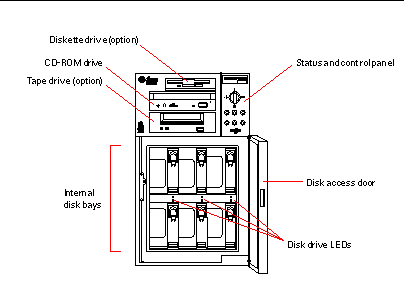
The illustration below shows the system features that are accessible from the front panel with the disk access door open.
Figure 1-1

For more information about front panel controls and indicators, see "About the Status and Control Panel".
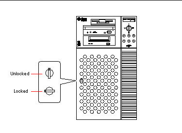
Access to the system's internal disk drives is through a large hinged door at the front of the system. The disk access door features a key lock for added security.
When the key is in the vertical position, the door is unlocked. Make sure that the key is in this position before you close the door. To lock the door, simply turn the key 90 degrees counterclockwise and remove the key. This same key also controls the front panel keyswitch.
Figure 1-2

Locating Rear Panel Features
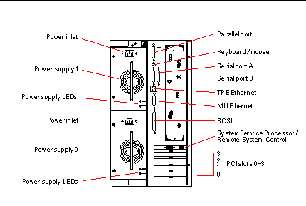
The illustration below shows the system features that are accessible from the rear panel.
Figure 1-3

Systems may be configured with one or two power supplies, which are accessible from the system rear panel. Each power supply has two LED indicators for displaying power status and fault conditions. See "Power Supply LEDs" for additional details.
A grounding screw is located in the upper-left corner of the rear panel. When connecting a deskside Enterprise 250 server to any rack-mounted peripheral, be sure to connect an appropriate grounding strap between the server's grounding screw and the rack enclosure. A grounding strap prevents ground loops between the two systems and guards against possible data loss.
About the Status and Control Panel
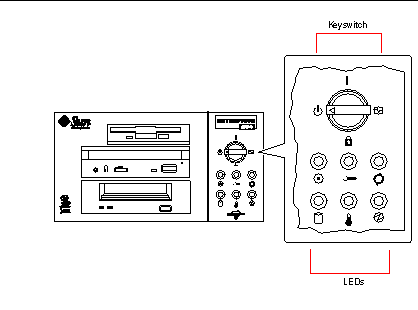
The status and control panel includes six LED indicators and a security keyswitch. The panel is located in the top-right corner of the system front panel, as shown in "Locating Front Panel Features".
Figure 1-4

The front panel keyswitch controls the power-on mode of the system. The following table describes the function of each switch setting.
Table 1-1|
Name |
Icon |
Description |
|---|---|---|
|
Power-On |
Turns the system power on. |
|
|
Diagnostics |
Turns the system power on and runs power-on self-test (POST) and OpenBoot(TM) diagnostics (OBDiag).
Turn the switch to this setting when you want to run POST and OBDiag at power-up. For more information on POST and OBDiag, see "About Diagnostic Tools". |
|
|
Locked |
Turns the system power on and disables the keyboard Stop-a command and terminal Break key command. This prevents users from suspending system operation and accessing the system ok prompt in order to modify OpenBoot configuration parameters stored in the system's nonvolatile memory.
This setting also prevents unauthorized programming of the system flash PROM. For additional details, see "About Flash PROM Jumpers".
This is the recommended setting for normal day-to-day operation of the system. |
|
|
Standby |
Places the system in standby mode by turning off power to all internal system components and placing the power supplies in standby mode. When the keyswitch is in this position, the keyboard power switch is disabled. |
The LEDs consist of two types: system health indicators and fault indicators. The system health indicators light to show you that the system is functioning normally. The fault indicators light when a problem is detected in the system. Because it is important for you to know that a fault exists in the system, the fault indicators remain lit when the system is reset or switched to standby mode using the keyswitch.
When you first power on the system, the LEDs are individually toggled on and off to verify that each one is working correctly. After that, the LEDs operate as described in the following table.
Table 1-2|
Name |
Icon |
Description |
|---|---|---|
|
Power-on |
This green LED lights steadily when the system power is on and the keyswitch is in the On, Diagnostics, or Locked position. |
|
|
General fault |
This yellow LED blinks slowly while the system runs its power-on self-test (POST) diagnostics and blinks rapidly during OpenBoot diagnostic (OBDiag) tests. It lights steadily when any fault is detected (including a fault also reported by any other LED). |
|
|
Activity |
This green LED blinks continuously to indicate that the system is operating normally. |
|
|
Disk fault |
This yellow LED lights steadily to indicate a fault in one of the hard disk drives. When this LED is lit, one or more disk LEDs may also be lit, indicating the source of the fault. |
|
|
Temperature fault |
This yellow LED lights steadily to indicate an over-temperature condition in the system. |
|
|
Power supply fault |
This yellow LED lights steadily to indicate a power supply fault. LEDs on the rear of the power supply indicate the nature of the fault (and identify which supply is faulty in a system with two supplies). |
- © 2010, Oracle Corporation and/or its affiliates
