Chapter 3 System Setup
This chapter explains how to attach all cords and cables needed to get the Sun Enterprise 250 server up and running. Where software is involved, this chapter explains some of what you need to do, and points you to the appropriate software manuals for the rest.
Tasks covered in this chapter include:
Other information covered in this chapter includes:
About the Parts Shipped to You
Your system is "configured-to-order," which means that most internal options that you order are pre-installed at the factory. However, if you ordered options that are not factory-installed (such as a monitor), these will be shipped to you separately.
In addition, you should have received the media and documentation for all appropriate system software (ordered separately). Check that you've received everything you ordered.
Note -
Inspect all shipping cartons for evidence of physical damage. If a shipping carton is damaged, request that the carrier's agent be present when the carton is opened. Keep all contents and packing material for the agent's inspection.
Unpacking instructions are printed on the outside of the shipping carton.
Save the original shipping containers and packing materials in case you need to store or ship your system. If you cannot store the shipping materials, recycle or dispose of the materials properly. Consult your local recycling authority for information.
How to Install the Enterprise 250 Server
Before You Begin
The Sun Enterprise 250 server is a general-purpose server, which you can use for many types of applications. Exactly how you set up your machine depends in some measure upon what you want it to do.
This procedure is intended to be as "generic" as possible, so as to cover the needs of most sites. Even so, you will need to make certain decisions to complete the procedure:
-
On which network or networks do you intend your machine to operate?
For background information about network support, see "About Network Interface Options".
-
How do you want to use/configure your machine's internal disk array?
For background information about internal disk array use, see "About Disk Array Configurations and Concepts".
-
What software do you intend to load?
Software included in the server media kit or other software products may impose certain disk space or disk partitioning requirements. Refer to the documentation accompanying this software to determine those requirements.
Once you've answered these questions, you're ready to begin.
What to Do
-
Verify that you've received all the parts of your system.
-
Ensure that the system's front panel keyswitch is in the Standby position.
-
Connect the AC power cord to the power inlet at the rear of the power supply. Connect the other end to a grounded AC power outlet.
The outlet must connect the system to a 15A circuit for North America and Japan, and to a 10A circuit for Europe. See your local electrical codes.
Insert the female end of the power cord through the plastic tie-wrap loop located to the right of the supply. Tighten the tie-wrap to secure the connection.
Figure 3-1
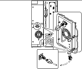
Note -If your server includes a second power supply, connect its AC power cord in the same manner. You may connect the second power supply to the same circuit as the first supply. However, for increased system redundancy, you should connect the two power supplies to separate circuits.
-
Install any optional components shipped with your system.
Many of the options ordered with your system may have been pre-installed at the factory. However, if you ordered options that were not factory-installed, see the following sections for installation instructions:
-
Set up a console for your server.
You must either attach an ASCII terminal to serial port A or else install a graphics card and attach a monitor, mouse, and keyboard. For more information, see "About Setting Up a Console".
-
Configure the serial port jumpers, if necessary.
Two serial port jumpers located on the main logic board are used to configure the system's serial ports A and B for either EIA-423 or EIA-232D signal levels. The jumpers are factory-set for EIA-423 levels, which is the default standard for North American users. EIA-232D levels are required for digital telecommunication in nations of the European Community. If you require EIA-232D signal levels, see the following sections for configuration instructions:
-
Configure the network interface.
The system's standard network interface is a switchable 10BASE-T/100BASE-TX Ethernet interface conforming to the IEEE 802.3u Ethernet standard. The interface configures itself automatically for either 10-Mbps or 100-Mbps operation, depending on network characteristics.
Supported PCI cards allow connection to additional Ethernet networks, or to token ring, FDDI, or other network types.
-
If you're using the standard Ethernet interface, see "How to Configure the Standard Ethernet Interface".
-
If you're using a PCI network interface, see the documentation accompanying the PCI network card.
-
-
Install the security lock block to prevent unauthorized removal of the side access panel, if required.
-
Turn on power to your server.
See "How to Power On the System". For information about the LED status indicators that appear during power-up, see "About the Status and Control Panel".
-
Install and boot the operating system software.
See the installation manual accompanying your Solaris software. Also read the SMCC SPARC Hardware Platform Guide, which contains platform-specific information about software installation. The operating system software is ordered separately from your system hardware.
-
Load additional software from the server media kit.
The server media kit (sold separately) includes several CD-ROM discs containing software to help you operate, configure, and administer your server. This software may include:
-
Solaris 2.x
-
Updates for Solaris Operating Environment for Sun Microsystems Computer Company
-
Solaris Desktop
-
Solstice(TM) DiskSuite(TM)
-
Solstice(TM) AdminSuite(TM)
-
Solstice(TM) AutoClient(TM)
-
Solstice(TM) Backup(TM)
See the appropriate documents provided in the server media kit for a complete listing of included software and detailed installation instructions.
-
-
Load the Sun Enterprise 250 Server Hardware AnswerBook(TM) online documentation.
See the installation instructions that accompany this CD-ROM disc in the Sun Enterprise 250 documentation set.
-
Decide on your internal disk array configuration.
For information about possible configurations, see "About Disk Array Configurations and Concepts".
How to Install the Security Lock Block
The security lock block supplied with the system is designed to prevent unauthorized removal of the system's side access panel.
What to Do
-
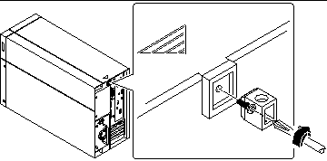
Attach the lock block to the side access panel at the top center of the system rear panel.
Use the captive Phillips screw and washer provided with the lock block.
Figure 3-2
-
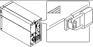
Install a padlock or combination lock through the lock block to prevent unauthorized removal of the side access panel.
To secure the power supplies as well, loop a cable through the lock block and through each power supply handle. Secure the cable with a padlock or combination lock.
Figure 3-3
About Setting Up a Console
To install your server or to diagnose problems, you need some way to enter system commands and view system output. There are four ways to do this.
-
Attach an ACSII character terminal to serial port A.
You can attach a simple terminal to serial port A. The terminal can be capable of displaying and entering alphanumeric but not graphical data. For instructions, see "How to Attach an Alphanumeric Terminal".
-
Establish a tip connection from another Sun system.
For information about establishing a tip connection, see the OpenBoot 3.x Command Reference Manual, an online version of which is included with the Solaris System Administrator AnswerBook that ships with Solaris software.
-
Install a local graphics console on your server.
The server is often shipped without a mouse, keyboard, monitor, or frame buffer for the display of graphics. To install a local graphics console on a server, you must install a graphics frame buffer card in a PCI slot, and attach a monitor, mouse, and keyboard to the appropriate back panel ports. For detailed instructions, see "How to Configure a Local Graphics Console".
-
Set up a Remote System Control (RSC) console.
Remote System Control (RSC) is a secure server management tool that lets you monitor and control your server over modem lines or over a network. RSC provides remote system administration for geographically distributed or physically inaccessible systems. For additional details, see "Remote System Control (RSC)".
How to Attach an Alphanumeric Terminal
Before You Begin
If your server is configured without a local graphics console, you need to attach an alphanumeric terminal (or establish a tip connection) to the server in order to install the system and to run diagnostic tests. For background information, see "About Setting Up a Console".
Alternatively, you can install a local graphics console on the server; see "How to Configure a Local Graphics Console".
For information about establishing a tip connection, see the OpenBoot 3.x Command Reference Manual, an online version of which is included with the Solaris System Administrator AnswerBook that ships with Solaris software.
What to Do
-
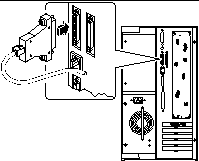
Connect the terminal's data cable to serial port A on the server's rear panel.
Figure 3-4
-
Connect the terminal's power cable to an AC outlet.
-
Set the terminal to receive:
-
At 9600 baud
-
An 8-bit signal with no parity and 1 stop bit
-
See the documentation accompanying your terminal for more information.
What Next
You can now issue system commands and view system messages. Continue with your installation or diagnostic procedure as needed.
How to Configure a Local Graphics Console
Before You Begin
If your server is configured without a local graphics console, you need to install one in order to install the system and to run diagnostic tests. For background information, see "About Setting Up a Console".
Alternatively, you can attach an ASCII terminal (or modem line) to the system's serial port; see "How to Attach an Alphanumeric Terminal".
To install a local graphics console, you must have:
-
A supported PCI-based graphics card
-
A monitor (CRT) with appropriate resolution
-
A Sun-compatible keyboard
-
A Sun-compatible mouse and mouse pad
What to Do
-
Install the graphics card in a vacant PCI slot.
-
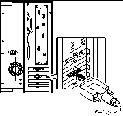
Attach the monitor video cable to the graphic card's video port.
Tighten the thumbscrews to secure the connection.
Figure 3-5
-
Connect the monitor's power cord to an appropriate AC power outlet.
-
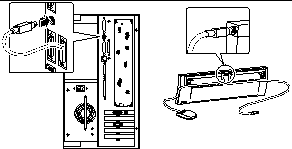
Attach the keyboard cable to the server's keyboard/mouse port.
Figure 3-6
-
Attach the mouse cable to the appropriate receptacle on the keyboard.
What Next
You can now issue system commands and view system messages. Continue with your installation or diagnostic procedure as needed.
- © 2010, Oracle Corporation and/or its affiliates
