| C H A P T E R 1 |
|
Parts Removal and Installation |
This chapter contains procedures for replacing the internal hardware components for the Sun Fire V125 server. The procedures in this section are for qualified service engineers only.

|
Caution - Read Section 1.8, System Configuration Card Reader, and wear a properly grounded antistatic strap, before you carry out any of the procedures in this document. |
The chapter contains the following sections:
Replaceable components in the front of the server are:
The remaining replaceable components are in the back of the server.
Before you carry out the procedures covered in this document, the server must be powered down. To do this you must remove the power cable. Follow the instructions in Section 1.2.2, Powering Off the Server.
The On/Standby button does not power off the server, but it toggles the server between On and Standby mode.

|
Caution - Never move the system when the system power is on. Movement can cause catastrophic drive failure. Always power off the system before moving it. |
1. Connect the server to an AC power source.
Once connected, the server automatically goes into Standby power mode.
2. Turn on power to any peripherals and external storage devices you have connected to the server.
Read the documentation supplied with the device for specific instructions.
4. Press the On/Standby switch.
1. Notify users that the system will be powered down.
2. Back up system files and data.
3. Press and release the On/Standby switch behind the bezel.
The system begins an orderly software system shutdown.
4. Wait for the front panel green indicator to go out.

|
Caution - As long as the power cord is connected, potentially hazardous energy is present inside the server. |
5. Disconnect the power cable.
This is the only way to remove power from the server. Electrical power is present when the server is in Standby mode.
Whenever you work with the server's internal components, follow this procedure to prevent damage caused by static electricity.
See Section 1.2, Controlling Server Power.
2. Open the back section of the cover.
See Section 1.4, Opening the Server.
3. Attach one end of the antistatic strap to the grounding stud located on the partition inside the server, and the other end to your wrist.
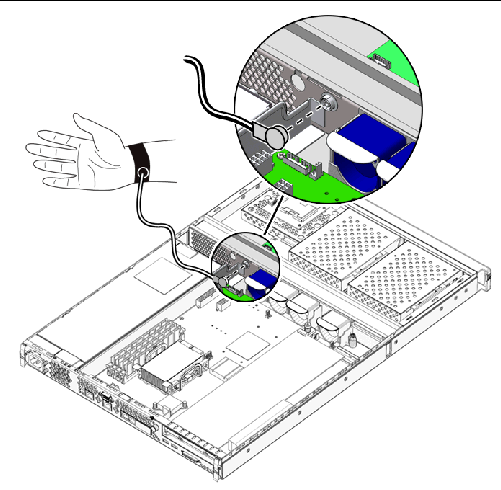
See Section 1.2, Controlling Server Power.
2. Perform either Step a or Steps b and c.
a. Attach one end of the antistatic strap to a grounding point on the rack and the other to your wrist.
b. Remove the server from the rack.
c. Place the server on an antistatic mat or other suitable antistatic surface.
Suitable antistatic surfaces include:
The cover of the server is split into two sections, front and back.

|
Caution - Disconnect the power cord before carrying out this procedure. As long as the power cord is connected, potentially hazardous energy is present inside the server. |

|
Caution - After servicing, install and fasten the cover before plugging in the power cords or turning power on. |
2. Undo the screws that fasten the front section of the cover to the chassis (FIGURE 1-2).
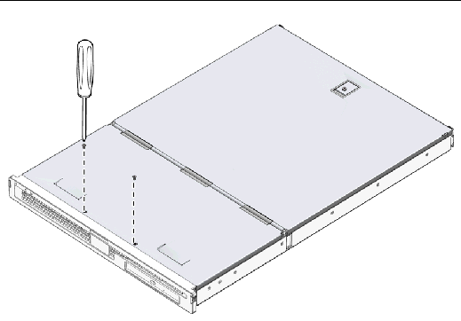
3. Slide the front section of the cover towards the front of the server.
Use the indentations in the cover to provide grip if necessary.
4. Lift off the front section of the cover (FIGURE 1-3).
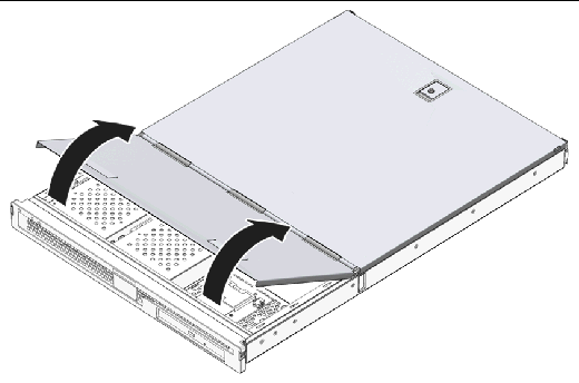
1. Align the clips on the bottom of the cover with the corresponding slots in the server chassis.
2. Press the cover down into the slots.
3. Slide the cover towards the back of the server.
4. Replace the screws that fasten the cover to the server.
1. Locate the latches at the back of the server and release them (FIGURE 1-4).
2. Undo the captive Phillips screw in the catch on top of the server (FIGURE 1-4).
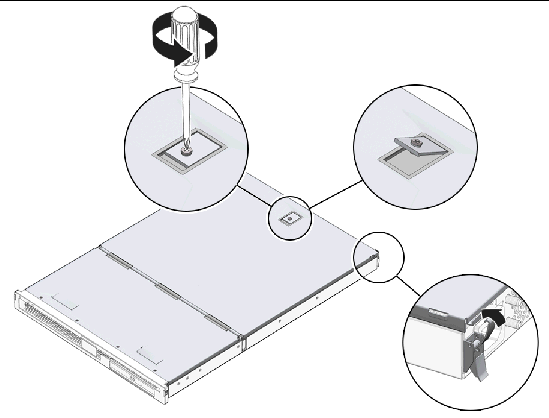
3. Pull the lever to release the catch and lift the cover up, pulling from the center and one corner of the cover.
The cover hinges forward to lay flush against the front section of the server.
1. Rotate the cover back to its closed position.
Ensure that the catch clips the cover into its closed position.
2. Tighten the captive screw in the catch on the cover.
3. Secure the cover using the clips on the outside of the server.
1. Remove the front section of the cover assembly.
See Section 1.4.1, Removing the Front Section of the Cover Assembly.
2. Open the back section of the cover assembly.
See Section 1.4.3, Opening the Back Section of the Cover Assembly.
3. Remove the back section of the cover assembly.
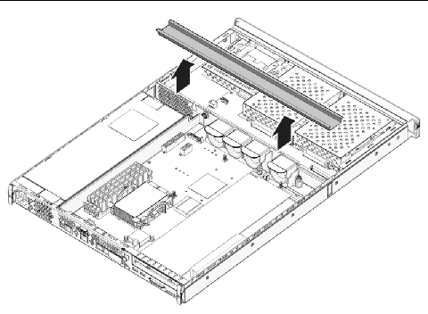
4. Unclip the U-channel that runs across the server and remove it (FIGURE 1-5).
You must remove this bar to reach the cables that connect the front of the server to the rear.
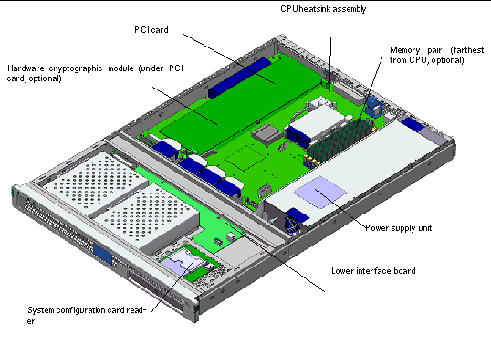
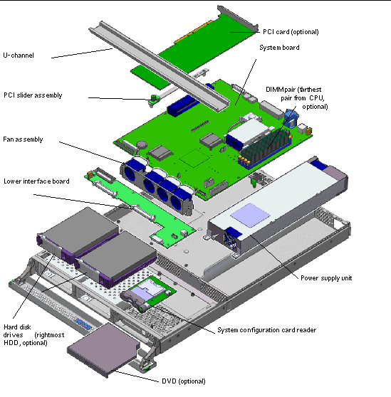
The internal components of the server are located in FIGURE 1-6.
The front bezel assembly includes the bezel, the front server status indicators, and hinges. The front bezel is replaced as a single unit.
See Section 1.2, Controlling Server Power.
2. Ensure that the server is properly grounded.
See the instructions in Section 1.3, Avoiding Electrostatic Discharge.
3. Hold the bezel firmly at both ends and rotate it down to its open position.
Grip the bezel at the points marked by the green triangles at each end to open it. Do not attempt to open the bezel using a single gripping point or by holding the middle of the bezel, as damage may occur.
4. Disconnect the cable connecting the bezel assembly to the server.
5. Unscrew the bezel hinges and remove them from the server.
1. Locate the new bezel and hinges onto the server, and screw the bezel hinges to the server.
For information on removing a hard drive while the operating server is running, see the Sun Fire V125 Server Administration Guide.
1. Ensure that you are properly grounded.
See Section 1.3, Avoiding Electrostatic Discharge.
3. Check that the blue indicator indicator is lit on the hard drive.
The blue indicator comes on when the hard drive is ready to remove.
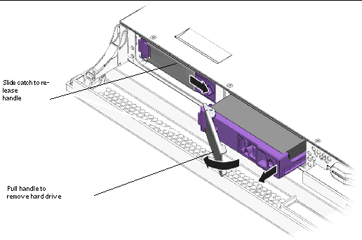
4. Slide the catch at the front of the hard drive to the right (FIGURE 1-7).
The handle on the front of the hard drive releases.
5. Pull the handle and remove the hard drive from the server by sliding the drive out from its bay.
|
Note - Note that in the preceding graphic, the standard configuration includes only the leftmost HDD; the second HDD is optional. |
1. Slide the catch on the front of the hard drive to the right.
This releases the hard drive. The lever must be open before you insert the hard drive into the server. If the lever is closed, the hard drive will not correctly engage.
2. Slide the hard drive into its bay at the front of the server.
Push the drive in firmly until the metal lever starts to close. The hard drive has engaged with its connector in the server.
3. Push the metal lever until the hard drive clicks into place.
For more information on the function of the system configuration card, see the Sun Fire V125 Server Administration Guide.
See Section 1.2, Controlling Server Power.
2. Ensure that the server is properly grounded.
See Section 1.3, Avoiding Electrostatic Discharge.
3. Remove the front section of the cover assembly.
See Section 1.4, Opening the Server.
4. Remove the system configuration card.
Place the system configuration card aside (FIGURE 1-9).
5. Disconnect the cable leading to the lower interface board from the configuration card reader (FIGURE 1-8).
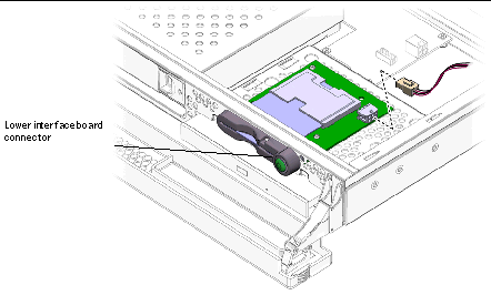
6. Unclip the system configuration card reader (FIGURE 1-9).
Hold the reader board firmly and unclip one corner at a time by pulling up. Take care not to damage the On/Standby switch when you remove the assembly.
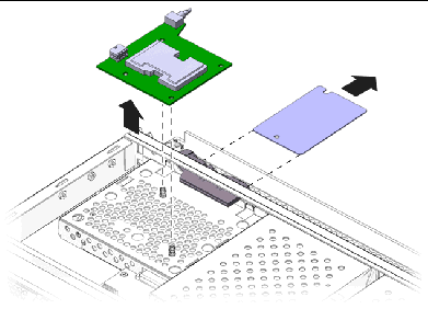
1. Position the new configuration card reader board by lining up the fixing holes with the clips in the top of the DVD drive enclosure.
2. Press the new reader board firmly onto the clips to secure it in place.
3. Reconnect the system configuration card reader power cable.
4. Install the system configuration card.
See Section 1.2, Controlling Server Power.
2. Ensure that the server is properly grounded.
See Section 1.3, Avoiding Electrostatic Discharge.
See Section 1.4, Opening the Server.
4. Disconnect the cables leading to the system board and interface board.
To access the cable connector to the interface board, open the front cover assembly.
5. Undo the two screws on the back panel of the server.
6. Move the PSU towards the front of the server to release it from the locating tab on the base of the server.
7. Lift the PSU out of the chassis.
1. Position the new PSU over the location tab and slide it towards the back of the server.
2. Install and tighten the two screws on the back panel of the server.
3. Connect the power supply wiring harness to the connectors on the system board and interface board.
4. Install the cover assembly.
There are four memory module sockets per processor on the system board. Memory is supplied by Sun in pairs. Use the DIMM pair as supplied and do not mix DIMMs.
For a list of the available memory options, see the Sun Fire V125 Server Administration Guide.
Memory is shipped in matched pairs for use on the Sun Fire V125 server.
When you install memory into a Sun Fire V125 server, follow the se guidelines:
1. Power down the server and disconnect the power cable.
See Section 1.2, Controlling Server Power
See Section 1.4.3, Opening the Back Section of the Cover Assembly.
3. Locate the correct DIMM socket.
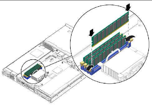
4. Ensure that the retaining clips are open (FIGURE 1-10).
5. Press the memory module in the DIMM socket.
6. Press down until the clips snap into place.
|
Note - Note that the second DIMM pair shown in the preceding figure is optional. The standard configuration includes only the DIMM pair that is closest to the CPU. |
1. Power down the server and disconnect the power cable.
See Section 1.2, Controlling Server Power.
See Section 1.4.3, Opening the Back Section of the Cover Assembly.
3. Locate the correct DIMM socket.
4. Open the latches at the sides of the socket.
5. Remove the module from the DIMM socket.
The Sun Fire V125 server has four 40 mm fans mounted side by side. Three of these cool the system board, while the fourth cools the PCI card area. All of these fans plug into the system board individually. The fans can be removed from the server without the use of tools.
1. Open the back section of the cover.
See Section 1.4, Opening the Server.
2. Disconnect the fans' power cables from the system board (FIGURE 1-11).
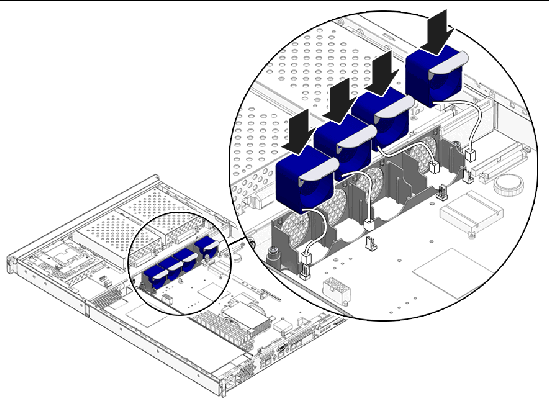
3. Push back the fan retaining tab.
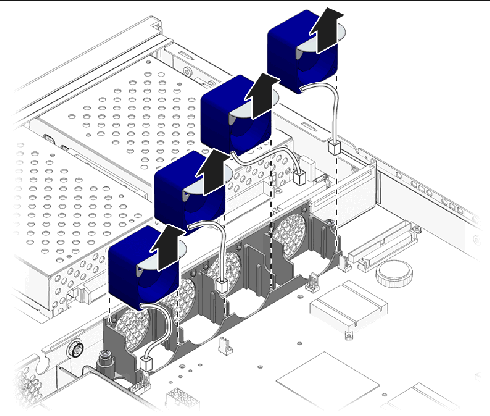
4. Lift the fan out of the chassis (FIGURE 1-12).
Pull on the tab on top of the fan assembly.
1. Insert the replacement fan.
2. Connect the fan's power cable to the system board.
3. Install the back section of the cover.
The CPU, heatsink, and system board are replaced as a single assembly.
|
Tip - To perform the steps in this section, you need a 5 mm wrench to remove and install the SCSI pillars and the DB-9 jackposts. |
See Section 1.2, Controlling Server Power.
2. Ensure that the server is properly grounded.
See Section 1.3, Avoiding Electrostatic Discharge.
3. Open the back section of the cover.
See Section 1.4, Opening the Server.
4. Disconnect the power supply wiring harness from the system board.
5. Disconnect the interface board SCSI and IDE cables from the system board.
6. If any PCI cards are fitted, remove them.
See Section 1.14.1, Adding a PCI Card.
7. Remove the PCI slider assembly.
8. Remove the server fan assembly.
9. Unscrew and remove the DB-9 and SCSI jackposts on the server's back panel.
The system board is secured to the chassis by ten screws.
11. Slide the system board toward the front of the chassis so that the SCSI, Ethernet, and serial connectors come free from the chassis.
12. Lift the system board out of the chassis.
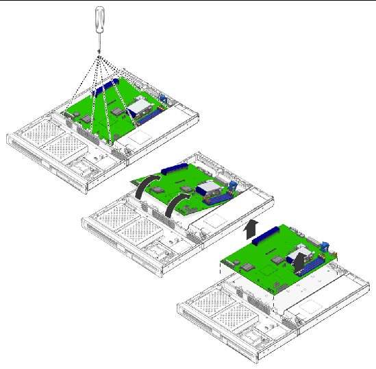
1. Insert the new system board and locate it so that the SCSI, Ethernet, and serial connectors are firmly positioned in their slots at the back of the chassis.
2. Insert all system board screws loosely.
Do not put any screws in the holes for the PCI card slide retainer. These holes are identified by a circle printed around their circumference.
3. Install the PCI slider assembly.
The arrow embossed on the slider should point to the rear of the server.
4. Install any PCI cards you removed.
5. Reconnect all system board cables and wiring harnesses.
6. Install the server's cover and tighten the screws.
The interface board assemblies handle the connections between the system board and the components in the front section of the server. The assemblies are positioned in the front section of the server, behind the hard drives and system configuration card reader assembly.
See Section 1.2, Controlling Server Power.
2. Ensure that the server is properly grounded.
See Section 1.3, Avoiding Electrostatic Discharge.
4. Remove DVD drive, if one is fitted in the system.
See Section 1.4, Opening the Server.
6. Disconnect the system board cable.
8. Disconnect the system configuration card reader cable.
9. Unscrew the eight screws that secure the LIB to the server's chassis as shown in the following figure.
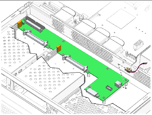
10. Lift the LIB assembly part of the way out of the server chassis.
11. Disconnect the cable from the bezel assembly.
12. Remove the LIB from the server.
1. Locate the new LIB assembly using the screw holes at each corner as guides.
The LIB printed circuit board (PCB) pushes onto (blind-mates) its connectors.
3. Attach the bezel PCB, PSU, and system board cables.
4. Install the cover assembly.
The PCI slot on the Sun Fire V125 server operates at 3.3 Vdc and supports one 64-bit PCI card running at 33 MHz or 66 MHz.
See Section 1.2, Controlling Server Power.
2. Ensure that the server is properly grounded.
See Section 1.3, Avoiding Electrostatic Discharge.
3. Open the back section of the server.
See Section 1.4, Opening the Server.
4. Unscrew the PCI lockdown screw on the back of the server.
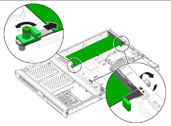
5. Remove the PCI lockdown bracket on the inside of the server.
6. Slide the PCI card support clear of the PCI card.
7. Disconnect and remove the PCI card.
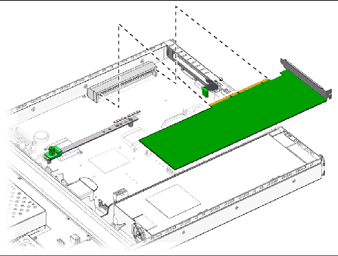
1. Locate the PCI card in the appropriate slot and press it firmly into the connector.
2. Locate the PCI card support so that it supports the back of the card.
3. Attach the PCI lockdown bracket and tighten the PCI lockdown screw.
The hardware cryptographic accelerator clips onto the server's system board. For more information, see the Sun Crypto Accelerator 1000 Installation and User's Guide.
1. Locate the clip that secures the cryptographic accelerator onto the system board.
2. Squeeze the clip to compress it.
3. Lift the cryptographic accelerator away from the chassis (FIGURE 1-18).
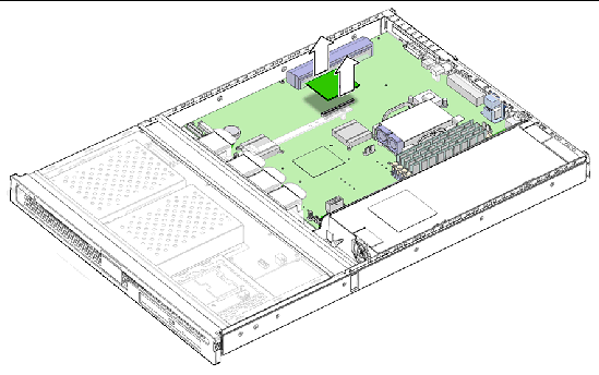
1. Press the standoff into the motherboard.
2. Place the cryptographic accelerator onto the standoff and connector on the motherboard.
3. Press the accelerator into place.
The battery powers the server's internal real time clock (RTC).
|
Tip - When replacing the battery, only use an identical replacement part. |
See Section 1.2, Controlling Server Power.
2. Ensure that the server is properly grounded.
See Section 1.3, Avoiding Electrostatic Discharge.
3. Open the back section of the cover.
See Section 1.4, Opening the Server.
4. Unclip the battery from its housing on the system board.
Push the retaining clip to one side to release the battery.
5. Locate the new battery in the housing and press down to secure it in place.
Copyright © 2006, Sun Microsystems, Inc. All Rights Reserved.