| C H A P T E R 2 |
|
Removing and Replacing Components |
This chapter tells you how to remove and replace the components that are located behind the server's front bezel. The procedures documented in this chapter do not require the attention of qualified service personnel.

|
Caution - Read the section, Section 2.2, Avoiding Electrostatic Discharge, and wear a properly grounded antistatic strap, before you carry out any of the procedures in this section. |
The chapter contains the following sections:
Open the bezel to access these components:
|
Note - Access to any other component requires the removal of the server's lid, and involves procedures that must be carried out by trained personnel only. |
1. Attach one end of the antistatic wrist strap to your wrist.
2. Attach the other end to a grounding stud on the rack or cabinet.
1. Ensure that you are properly grounded.
See Section 2.2.1, Avoiding Electrostatic Discharge While Working on the Front Panel.
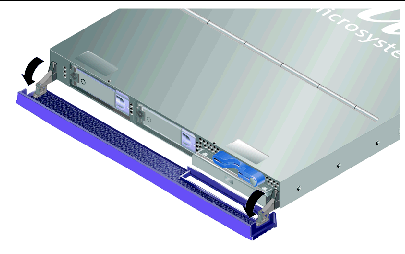
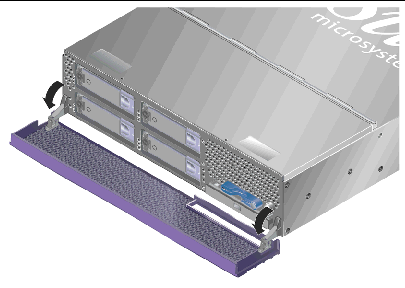
2. Open the bezel by rotating it down on its hinges.
|
Note - Always grip the bezel at both ends to open it. Do not attempt to open it using a single point of grip. |
Before you remove or replace a system configuration card or DVD-ROM drive, the server must be powered down.
|
Tip - For detailed information on controlling server power with software, see:
|

|
Caution - Never move the system when the system power is on. Movement can cause catastrophic disk drive failure. Always power off the system before moving it. |
1. Connect the server to an AC power source.
Once connected, the server automatically goes into Standby power mode.
2. Turn on power to any peripherals and external storage devices you have connected to the server.
Read the documentation supplied with the device for specific instructions.
4. Sun Fire V240 only: insert the system key into the keyswitch and set it to the Normal or Diagnostics position.
5. Press the On/Standby switch.
Verify that the LED for the On/Standby switch illuminates.
a. Turn the key switch to the Locked position.
This prevents anyone from accidentally powering off the system.
b. Remove the system key from the keyswitch and store it in the clip on the back of the bezel.
|
Note - Applications running on the Solaris OS can be adversely affected by a poorly executed system shutdown. Make sure you have gracefully shut down any applications before powering off the system. |
1. Notify users that the system will be powered down.
2. Back up the system files and data, if necessary.
3. (Sun Fire V240 only) Ensure that the keyswitch is in the Normal or Diagnostics position.
4. Press and release the On/Standby switch behind the front bezel.
The system begins an orderly software system shutdown.
5. Wait for the front panel green LED to go out.
6. Sun Fire V240 only: remove the system key from the keyswitch and store it in the clip on the back of the front bezel.
See Section 2.3, Controlling Server Power.
2. Open the front bezel on both servers.
See Section 2.2.2, Opening the Front Bezel.
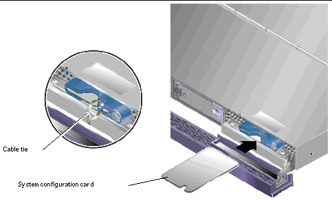
3. Remove the cable ties that secure the system configuration cards, and remove the cards.
4. Insert the system configuration card from the old server into the new one.
5. Replace the cable tie on the new system.

|
Caution - The server and hard drives contain electronic parts that are extremely sensitive to static electricity. Wear a grounded antistatic wrist strap when you carry out this procedure. |
The hard drives are hot-pluggable modules. If more than one is fitted, you can install or remove a hard drive without powering off the server or removing it from the rack.
However, you do need to make sure that no system or application software is using a hard drive when you remove it.
|
Note - If you intend to remove a hard drive with Solaris running, follow the instructions in Section 2.5.4, Removing a SCSI Hard Drive With Solaris Running before performing the following steps. |
See Section 2.2.2, Opening the Front Bezel.
2. Check that the blue indicator LED is lit on the hard drive.
The blue LED comes on when the hard drive is ready to remove.
3. Slide the catch at the front of the hard drive to the right.
This releases the handle on the front of the hard drive.
4. Pull the handle and remove the hard drive from the server by sliding it out from its bay.

|
Caution - The server and hard drives contain electronic parts that are extremely sensitive to static electricity. Wear a grounded antistatic wrist strap when you carry out this procedure. |
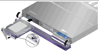
1. Slide the catch on the front of the hard disk to the right.
This releases a handle on the front of the hard drive. The lever must be open before you insert the hard drive. If it is not, the hard drive does not engage with the server correctly.
2. Slide the hard drive into its bay at the front of the server.
Push it in firmly until the metal lever starts to close. This indicates that the hard drive is engaged with its connector attached to the server.
3. Push the metal lever until the disk drive clicks into place.
If you have installed a hard drive with Solaris running, perform the steps in Section 2.5.3, Installing a SCSI Hard Drive With Solaris Running.
Before performing the instructions in this section, install the hard drive by following the instructions in Section 2.5.2, Replacing a Hard Drive.
Use the following instructions in conjunction with the cfgadm(M) man page.
1. With the new hard drive physically installed in the drive bay, log into the system as superuser and run the format command to make the disk visible to the Solaris OS.
Type the following command. The following sample output is from a system containing two hard drives.
2. Find the label of the new hard drive, which appears in the Ap_Id column of the sample output. Type:
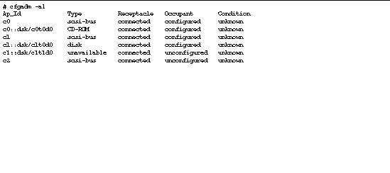
In this sample output, the new drive is Disk 1.
3. Connect the new drive logically to the operating system.
Type the following command, specifying the correct Ap_Id label for the disk you have installed. In this sample command the Ap_Id label is for Disk 1:
4. Confirm that the drive is now connected and configured. Type:
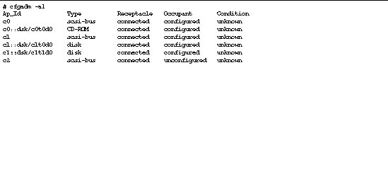
The disk is now available to be mounted for operation.
If you are removing a hard drive while the operating system is still running, you must remove the drive logically from the operating system before removing it physically. Follow the instructions in this section, then remove the hard drive physically by following the instructions in Section 2.5.1, Removing a Hard Drive.
Use the following instructions in conjunction with the cfgadm(M) man page.
1. Check that the hard drive you want to remove is visible to the Operating System.
2. Get the correct Ap_Id label for the hard drive that you want to remove. Type:
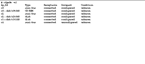
3. Unconfigure the hard drive that you intend to remove.
Use the unconfigure command and specify the device you intend to remove. For example, if it is Disk 1, type:
4. Verify that the device is now unconfigured. Type:
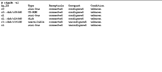
5. Confirm that the hard drive you want to remove from the server is no longer visible to the operating system. Type:
# format Searching for disks...done AVAILABLE DISK SELECTIONS: 0. c0t0d0 <SUN36G cyl 24427 alt 2 hd 27 sec 107> /pci@1f,0/pci@1/scsi@8/sd@0,0 |
It is now safe to remove the hard drive from the server without shutting down the operating system.
The DVD drive is not hot-swappable. The server must be powered down, and the power cable removed from the back panel, before you remove or install a DVD drive.
See Section 2.3, Controlling Server Power.
See Section 2.2.2, Opening the Front Bezel.
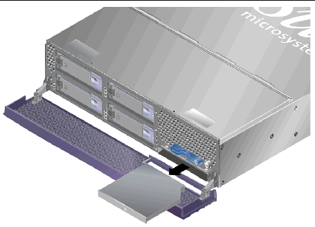
3. Unclip the catches that fasten the DVD drive to the chassis (FIGURE 2-5).
4. Pull the DVD drive towards you until it is free of its connectors and out of the chassis.
1. Insert the new DVD-ROM drive.
2. Press it home firmly until the clips engage with the server's chassis.
The Sun Fire V240 server has dual-redundant power supplies. You can swap one power supply while the other is still running.
The Sun Fire V210 server has a single power supply. Swapping it requires the attention of qualified service personnel. Refer to the Sun Fire V210 and V240 Servers Service Manual (819-4207-10).
Where x is the power supply unit identifier, 0 or 1.
When the blue ok to remove LED lights on the back of the power supply unit, remove it.
2. Pull down on the PSU lever.
3. Withdraw the PSU from the server's chassis.
1. Slide the PSU into the back of the server until it stops.
Do not push the PSU lever closed until the PSU is all the way in.
2. Press the PSU lever until it clicks home.
This engages the PSU with the power distribution board inside the server.
Where x is the power supply unit identifier, 0 or 1.
Copyright © 2004, Sun Microsystems, Inc. All Rights Reserved.