A P P E N D I X  A

DIMM and PCI Card Guidelines

This appendix describes DIMM and PCI configuration guidelines for the Sun Fire V215 and V245 Servers.

The following topics are covered:


A.1 DIMM Guidelines

Memory is shipped in matched pairs. Use the DIMM guidelines, FIGURE A-1, and TABLE A-1 to plan the memory configuration of your server.

DIMM pairs that have identical attributes, but different manufacturers, might cause OpenBoot PROM to issue the following warning message to the console:

ERROR: /memory: CPU1 Bank 0 DIMMs are from diff vendors

This condition will disable autoboot. However, the DIMMs will still be used. If you encounter this error message, you can boot the server manually.
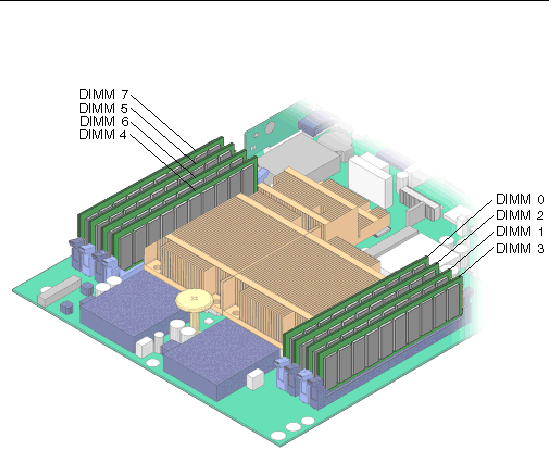
FIGURE A-1 DIMM Layout


Figure showing DIMM layout in the Sun Fire V215 and V245 Motherboard


TABLE A-1 DIMM Name, DIMM Number, DIMM Connector, and Connector Color

DIMM Name

DIMM Number

DIMM Connector

Connector Color

Rank 0

/MB/P0/B0/D0

DIMM 0

J5

Blue

(1 or 2 CPUs)

/MB/P0/B0/D1

DIMM 1

J2

Blue


/MB/P0/B1/D0

DIMM 2

J4

Black


/MB/P0/B1/D1

DIMM 3

J1

Black

Rank 1

/MB/P1/B0/D0

DIMM 4

J25

Blue

(2 CPUs)

/MB/P1/B0/D1

DIMM 5

J29

Blue


/MB/P1/B1/D0

DIMM 6

J27

Black


/MB/P1/B1/D1

DIMM 7

J30

Black


Note - DIMM names in messages are displayed with the full name such as /MB/P0/B0/D0/.


A.2 PCI-E and PCI-X Card Guidelines

The PCI expansion system is configured using a variety of riser cards. With the release of new optional riser cards in October 2007, the guidelines have been updated.

The following guidelines now apply for the Sun Fire V215 server:


TABLE 0-1 PCI Card Guidelines for the Sun Fire V215 Server

Riser

Type

Dimensions

Comments

1UXXL (left side)

PCI-X (slot 1)

Full height, half length[1]

133 MHz

1UEEL (left side)

PCI-E (slot 1[2])

Full height, half length\

Low profile, half length

Lane x8

Lane x8, slot x16

1UEER (right side)

PCI-E (slot 0)

Low profile, half length[3]

Lane x8, slot x16


The following guidelines now apply for the Sun Fire V245 server:


TABLE A-2 PCI Card Guidelines for the Sun Fire V245 Server

Riser

Type

Dimensions

Comments

2UEXL (left side)

PCI-X (upper slot 3)

PCI-X (lower slot 1)

Full height, full length[4]

Full height, half lengthd

133 MHz

133 MHz

2UEEL[5] (left side)

PCI-E (upper slot 3)

PCI-E (lower slot 1)

Full height, full lengthd

Full height, half lengthd

Lane x8, slot x16

Lane x8, slot x16

2UEER[6] (right side)

PCI-E (upper slot 2)

PCI-E (lower slot 0)

Low profile, half length

Low profile, half length

Lane x4, slot x16

Lane x4, slot x16


You can add only one riser card to the server. If you add the XVR-2500 graphics adapter, you must use the PCI-E riser card assembly that converts all of the PCI-X I/O slots to PCI-E slots. After installation, the I/O subsystem will be entirely PCI-E based (that is, no PCI-X slots will be available). The XVR-2500 graphics adapter and any PCI-X adapter, including the serial, asynchronous adapter (SAI/P), are mutually exclusive within the same system.


1 (TableFootnote) Low-profile cards fit with appropriate full-height faceplate.
2 (TableFootnote) If you add a 1U or 2U PCI-E riser card, you must remove the PCI-X riser card. The removal results in the loss of available slots for
PCI-X option cards.
3 (TableFootnote) 1UEER is factory installed in all systems.
4 (TableFootnote) Low-profile cards fit with appropriate full-height faceplate.
5 (TableFootnote) If you add a 1U or 2U PCI-E riser card, you must remove the PCI-X riser card. The removal results in the loss of available slots for
PCI-X option cards.
6 (TableFootnote) 2UEER is factory installed in all systems.