| Sun Fire V440 Server Setup: Cabling and Power On |
| Sun Fire V440 Server Setup: Cabling and Power On |
|
Sun Fire V440 Server Setup: Cabling and Power On |
This guide tells you how to route the cables and cords and power on the Sun Fire V440 server. Use this guide after you have installed the Sun Fire V440 server into a rack, following instructions either on the server's top panel or in the Sun Fire V440 Server Installation Guide. The illustrated instructions in this guide are a continuation of the the rackmount instructions on the Sun Fire V440 server top label. All installation instructions in full detail are included in the Sun Fire V440 Server Installation Guide and the Cable Management Arm Installation Note.
You should have completed the following tasks:
This document provides an overview of the following tasks:
The following figure shows the Sun Fire V440 server back panel and identifies the AC power inlet and I/O ports.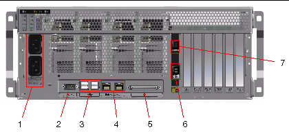
|
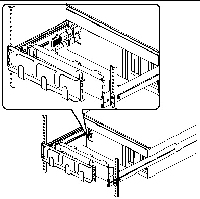
Note - Illustration does not show the cable management arm in place. |
1. Make sure that all cords and cables are slack enough to allow routing, yet taut enough to avoid obstructing the movement of the slide assemblies.
At a minimum, the server includes two power cords, an Ethernet cable, and a serial management cable.
2. Before you connect any cords or cables, thread them through the cable management arm.
3. Use the Velcro straps to secure the cords and cables to the cable management arm.
4. Plug in the Ethernet cable to the RJ-45 outlet to connect to your Ethernet network.
Contact your network administrator if you need more information.
1. Unlock the right system door.
2. Insert the system key into the system control keyswitch.
3. Ensure that the system control keyswitch is in the Standby position.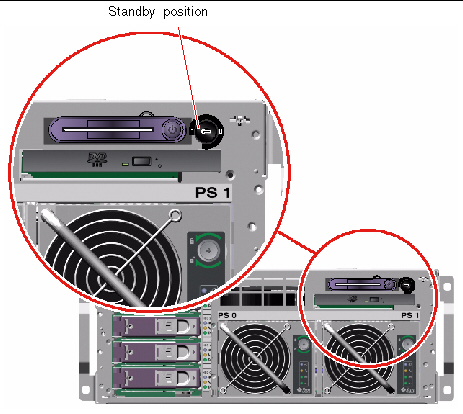
4. Connect an AC power cord to each AC inlet at the back of the server.
|
Note - Do not connect the cords to AC power outlets at this point. You connect the cords to AC outlets during a later step, after you have set up a system console device. |
Use the following steps to connect a twisted-pair Ethernet cable to one or both of the Ethernet ports on the back panel. See the Sun Fire V440 Server Administration Guide for more information about seeing up more than one network interface.
1. Choose a network port, using the following table as a guide.
2. Plug in a Category-5 unshielded twisted-pair cable to the appropriate RJ-45 connector. The cable length must not exceed 328 feet (100 meters). After power-on, the Ethernet Link/Activity LED (on the left) is lit, and the Speed LED (on the right) indicates arbitrated 1000-Mbps operation.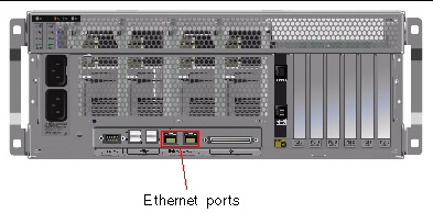
If you ordered options that are not factory-installed, see the Sun Fire V440 Server Parts Installation and Removal Guide for installation instructions.

|
Caution - To protect electronic components from electrostatic damage, note the following guidelines. |
When connected to the serial management port (SERIAL MGT) on the Sun Advanced Lights Out Manager (ALOM), different types of devices can serve as the interface to the system console. Among the devices:
Instructions for setting up a terminal server and for making it a tip connectionare in the Sun Fire V440 Server Installation Guide. following are instructions for setting up an alphanumeric terminal.
1. Remove the terminal's power plug from the AC outlet.
2. Connect one end of the serial cable to the terminal's serial port.
The Sun Fire V440 is a DTE machine. Use an RJ-45 serial cable or an adapter appropriate for your terminal. Plug in the cable to the terminal's serial port connector.
3. Connect the serial cable's RJ-45 connector to the Sun Fire V440 server.
Plug in the cable to the server's serial management port (SERIAL MGT), which is the upper RJ-45 port on the ALOM card.
4. Connect the terminal's power cord to an AC outlet and turn on the power.
5. Set the terminal to receive a 9600 baud, 8-bit signal with no parity and 1 stop bit.
The following instructions assume that you have chosen a network port and have installed an Ethernet cable.
1. Choose a host name for the server and make a note of it.
You need to furnish the host name at a later time, when you configure the network interface according to prompts from the SolarisTM Operating System (Solaris OS).
The host name must be unique within the network. It can consist only of alphanumeric characters and the dash (-). Do not use a dot in the host name. Do not begin the name with a number or a special character. The name must not be longer than 30 characters.
2. Determine the unique Internet Protocol (IP) address of the network interface and make a note of it.
You need to furnish the IP address at a later time, when you configure the network interface according to prompts from the Solaris OS.
An IP address must be assigned by the network administrator. Each network device or interface must have a unique IP address.
After you boot the server, you must still configure the primary network.
For other network devices to communicate with the server, you must enter the server's IP address and host name into the namespace on the network name server.
1. Unlock and open the right system door.
2. Insert the system key into the system control keyswitch and turn the system control keyswitch to the Diagnostics position.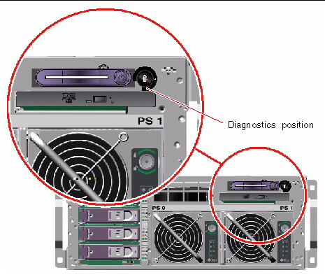
3. Connect the outlet plug of each power cord to the power sequencer in the cabinet, or to a grounded AC power outlet.
To ensure redundancy, connect cords to separate circuits or circuit breakers. The Standby LED for each power supply is lit, indicating that power is being supplied.
As soon as you plug in the power cords, several boot messages from the ALOM system controller are displayed on your system console device. The ALOM boot messages end with the following:
4. At the ALOM prompt (sc>), enter the following command:
5. When prompted, create and then confirm an administrator password.
Once again, the sc> prompt is displayed.
6. At the ALOM prompt (sc>) again type the console command:
The server runs full diagnostics, which can take several minutes. Because the auto-boot? parameter is true by default, the server will attempt to boot and install from the network. If no network boot server is found, the ok prompt is displayed.
See the Sun Fire V440 Server Installation Guide for instructions on how to perform an alternative power-on method. The Power OK LEDs on the back panel are lit when the power supply is turned on.

|
Caution - Never move the server when the server power is on. Movement can cause catastrophic disk drive failure. Always power off the server before moving it. |
You must have already set up a system console device before you can install the Solaris OS. See Setting Up a Console Device. Make sure that you have a supported version of the Solaris OS. See the Sun Fire V440 Product Notes for additional information.
1. Locate your Solaris Media Kit.
The Solaris Media Kit, in which you will find the Solaris OS CDs and additional software, must be ordered separately. Contact your Sun service provider if you do not have a Solaris Media Kit.
2. Install the Solaris operating sytem on your server.
Install the software using any of four methods, which are fully explained in the documentation included with the Solaris Media Kit:
3. Load additional software from the Supplement CD (optional).
See the documentation provided in the Solaris Media Kit for a listing of included software.
4. Install any software patches listed in the Sun Fire V440 Product Notes. The latest versions of the Product Notes are located on the Sun Web site, at http://www.sun.com/documentation.
A list of recommended patches recommended patches is also available on the SunSolve Online Web site at http://sunsolve.sun.com. You can obtain patches and installation instructions from your Sun service provider or by downloading them from the SunSolve Online web site. Staying current with all patches will give you access to better diagnostics and server performance.
5. Run the Sun Install Check tool to verify basic installation and configuration of your system.
Download the tool from the following URL:
http://www.sun.com/software/installcheck/index.html
Your Sun Fire V440 server is ready to use.
For more information, consult your Sun Fire V440 Server Documentation CD.
|
Customizing the Sun Advanced Lights Out Manager (ALOM) software |
Sun ALOM Online Help modules are are provided with the ALOM software. You can also access the ALOM help modules from your Documentation CD or from the ALOM Web site: http://www.sun.com/servers/alom.html |
| Sun Fire V440 Server Setup: Cabling and Power On | 816-7734-12 |
Copyright © 2005, Sun Microsystems, Inc. All Rights Reserved.