| A P P E N D I X A |
|
Installing RAID |
This appendix describes how to install and configure the Sun Fire V60x or Sun Fire V65x server Zero-Channel RAID card.
|
Note - The Solaris Intel Platform Edition operating system does not contain drivers for the Sun Fire V60x or Sun Fire V65x server Zero-Channel RAID card. |
This appendix contains the following sections:
This section is intended to allow you to quickly install RAID on your Sun Fire V60x or Sun Fire V65x server. It contains step-by-step instructions for installing an operating system on a single RAID volume using the hard disk drives already installed in the server. If you plan on using a different operating system, need a more advanced RAID configuration, or need safety and regulation information, please contact a Sun representative.
For additional background and details, please refer to the following sections of this appendix:
Following is a list of items you need to successfully complete a RAID installation on your server:
Follow these steps to install a RAID system on your server:
1. Make an OS installation diskette.
a. Boot the server from the RAID software CD.
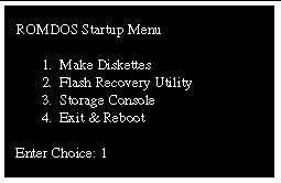
Select Make Diskettes from the ROMDOS Startup Menu that appears (see FIGURE A-1).
b. Create an operating system diskette for the OS you will be installing.
2. Install the zero-channel RAID controller board in the server.
b. Disconnect the server power cord(s).
c. Remove the server top cover.
d. Unplug and remove the full-height riser board from the server.
|
Note - The full-height riser board is the one on the left when the server is viewed form the front. |
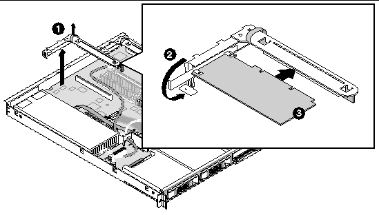
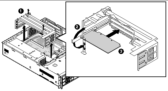
e. Install the zero-channel RAID controller in the full-height riser board, in the slot closest to the surface of the main board of the server (see FIGURE A-2).
|
Note - FIGURE A-2 shows installation of the controller in a 1U server. FIGURE A-3 shows installation of the controller in a 2U server. Make sure to install the controller in the slot closest to the server main board. |
f. Replace the riser board, with the RAID controller board in it.
|
Note - The RAID controller uses the SCSI controller on the server board to communicate with the drives, so no SCSI cables need to be connected to the controller board. |
3. Create a bootable host drive (RAID Volume).
|
Note - Refer to RAID Levels as needed to decide on your desired RAID configuration. |
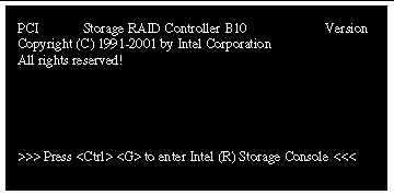
a. Power on the server and press <Ctrl> + <G> when the screen shown in FIGURE A-4 appears.
After you press <Ctrl>+<G>, the following two messages appear at the bottom of the screen:
Intel (R) Storage Console to start after POST
Please wait to start Intel (R) Storage Console
When the Storage Console software starts, it indicates that the RAID controller (SRCZCR) is installed in the server (see FIGURE A-5).

b. Press <Enter> to select the SRCZCR controller.
c. At the Express Setup window, select Configure Host Drives and press <Enter> (see FIGURE A-6).
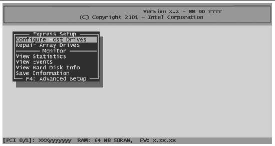
d. Select Create new Host Drive at the next window (see FIGURE A-7).

A list of available hard disk drives is displayed (see FIGURE A-8). These are drives that do not belong to a logical host drive and can be used for new RAID host drives.
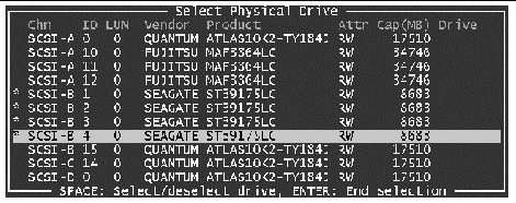
e. Use the arrow keys and the space bar to select the hard drives you wish to include in the RAID system (the ones that are available are marked
with an "*").
To select or deselect a drive, move the highlight over the drive with the arrow keys and press the space bar.
f. Press <Enter> when you are satisfied with your selections.
The Choose Type menu appears, offering various host type drives (see FIGURE A-9).
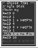
g. Select the host drive type (RAID 0, RAID 1, RAID 1 + HotFix, RAID 4, RAID 4 + HotFix, RAID 5, RAID 5 + HotFix, or RAID 10), and press <Enter>.
For security reasons, you are asked if you really want to use the disk(s) you selected in step 3e to create a host drive. A warning is displayed that all data on the disk(s) will be destroyed (see FIGURE A-10).

h. Press <Y> to confirm your choice.
The Storage Console software creates a new host drive, and a window is displayed that asks you to enter the appropriate drive capacity (see FIGURE A-11).

i. Enter the appropriate drive capacity and press <Y>.
A window is displayed that allows you to begin the host drive build process (see FIGURE A-12)

j. Press <F10> to refresh and begin the build process.
The status indicates "build" and does not change to "ready" until the RAID array has been built.
When leaving Storage Console (by pressing <Esc>), a progress window informs you about the estimated completion time for the build process.
When the build process successfully completes, the disk array changes to "idle" status.
This step requires that you enter into the server BIOS menu and set up the proper boot priority.
a. During POST, press <F2> when prompted to enter the BIOS Setup Utility.
b. Navigate to the Boot menu and select Boot Device Priority.
c. Set up the following boot order:
d. Press <Esc> to return to the previous screen.
e. Access the Hard Disk Drives submenu in the BIOS setup and make sure the Intel (R) RAID Host Drive is at the top of the priority list.
f. Press <F10> to save your BIOS changes and exit.
RAID installation is now complete. At this point, you must install the OS.
RAID (redundant array of independent disks; originally redundant array of inexpensive disks) is a way of storing the same data in different places (thus, redundantly) on multiple hard disks. By placing data on multiple disks, I/O operations can overlap in a balanced way, improving performance. Because having multiple disks increases the mean time between failure (MTBF), storing data redundantly also increases fault-tolerance.
A RAID system appears to the operating system to be a single logical hard disk. RAID employs the technique of striping, which involves partitioning each drive's storage space into units ranging from a sector (512 bytes) up to several megabytes. The stripes of all the disks are interleaved and addressed in order.
In a single-user system where large records, such as medical or other scientific images, are stored, the stripes are typically set up to be small (perhaps 512 bytes) so that a single record spans all disks and can be accessed quickly by reading all disks at the same time.
In a multi-user system, better performance requires establishing a stripe wide enough to hold the typical or maximum size record. This allows overlapped disk I/O across drives.
This section explains the various types of RAID configurations, or levels. Each RAID level has its advantages and disadvantages. Before you decide on the RAID level to set up on your server, you may want to read the following information.
|
Note - If you are already familiar with RAID systems, you may skip ahead to Preparing for Installation. |
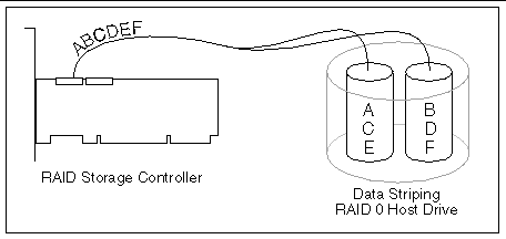
Data blocks are split into stripes based on the adjusted stripe size (for example, 128 KB) and the number of hard disks. Each stripe is stored on a separate hard disk (see FIGURE A-13). Significant improvement of the data throughput is achieved using this RAID level, especially with sequential read and write. RAID 0 includes no redundancy. When one hard disk fails, all data is lost.
All data is stored twice on two identical hard disks. When one hard disk fails, all data is immediately available on the other without any impact on performance and data integrity.
With Disk Mirroring (), two hard disks are mirrored on one I/O channel. If each hard disk is connected to a separate I/O channel, it is called Disk Duplexing (FIGURE A-15).
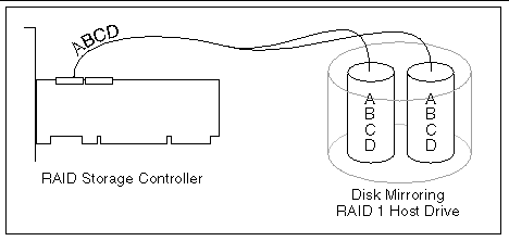
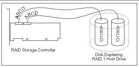
RAID 1 represents an easy and highly efficient solution for data security and system availability. It is especially suitable for installations which are not too large (the available capacity is only half of the installed capacity).
RAID 4 works in the same way as RAID 0. The data is striped across the hard disks and the controller calculates redundancy data (parity information) that is stored on a separate hard disk (P1, P2, ...), as shown in FIGURE A-16. Should one hard disk fail, all data remains fully available. Missing data is recalculated from existing data and parity information
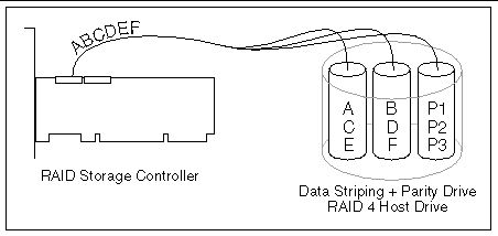
Unlike RAID 1, only the capacity of one hard disk is needed for redundancy. For example, in a RAID 4 disk array with 5 hard disks, 80% of the installed hard disk capacity is available as user capacity, and only 20% is used for redundancy. In systems with many small data blocks, the parity hard disk becomes a throughput bottleneck. With large data blocks, RAID 4 shows significantly improved performance.
Unlike RAID 4, the parity data in a RAID 5 disk array is striped across all hard disks (FIGURE A-17).
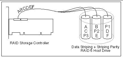
The RAID 5 disk array delivers a balanced throughput. Even with small data blocks, which are very likely in a muti-tasking and muti-user environment, the response time is very good. RAID 5 offers the same level of security as RAID 4. When one hard disk fails, all data is still fully available. Missing data is recalculated from the existing data and parity information. RAID 4 and RAID 5 are particularly suitable for systems with medium to large capacity requirements, due to their efficient ratio of installed and available capacity.
RAID 10 is a combination of RAID 0 (Performance) and RAID 1 (Data Security). See FIGURE A-18.
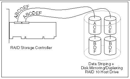
Unlike RAID 4 and RAID 5, there is no need to calculate parity information. RAID 10 disk arrays offer good performance and data security. As in RAID 0, optimum performance is achieved in highly sequential load situations. Identical to RAID 1, 50% of the installed capacity is lost through redundancy.
The IIR firmware is based on four fundamental levels of hierarchy. Each level has its "own drives" (components). The basic rule is to build up a "drive" on a given level of hierarchy. The "drives" of the next lower level of hierarchy are used as components.
Physical drives are hard disks and removable hard disks. Some Magneto Optical (MO) drives are located on the lowest level. Physical drives are the basic components of all "drive constructions." However, before they can be used by the firmware, these hard disks must be "prepared" through a procedure called initialization. During this initialization each hard disk receives information that allows an unequivocal identification even if the SCSI ID or the controller is changed. For reasons of data coherency, this information is extremely important for any drive construction consisting of more than one physical drive.
On the next higher level are the logical drives. Logical drives are introduced to obtain full independence of the physical coordinates of a physical device. This is necessary to easily change the IIR controller and the channel ID without losing the data and the information on a specific disk array.
On this level of hierarchy, the firmware forms the array drives. Depending on the firmware installed, an array drive can be:
On level 4, the firmware forms the host drives. Only these drives can be accessed by the host operating system of the computer. Hard disk drives (for example, C or D) under MSDOS are always referred to as host drives by the firmware. The same applies to NetWare and UNIX drives. The firmware automatically transforms each newly installed logical drive and array drive into a host drive. This host drive is then assigned a host drive number that is identical to its logical drive or array drive number.
The firmware is capable of running several kinds of host drives at the same time. For example, in MSDOS, drive C is a RAID 5 type host drive (consisting of 5 SCSI hard disks), drive D is a single hard disk, and drive E is a CD-ROM communicating with IIR firmware. On this level the user may split an existing array drive into several host drives.
After a capacity expansion of a given array drive, the added capacity appears as a new host drive on this level. It can be either used as a separate host drive, or merged with the first host drive of the array drive. Within RAID, each level of hierarchy has its own menu:
Level 1 - Configure Physical Devices
Level 2 - Configure Logical Drives
Level 3 - Configure Array Drives
Level 4 - Configure Host Drives
Generally, each installation procedure passes through these 4 menus, starting with level 1. Installation includes initializing the physical drives, configuring the logical drives, configuring the array drives (for example, RAID 0, 1, 4, 5, and 10), and configuring the host drives.
The structure of the host drives installed with StorCon is not known to the operating system. For example, the operating system does not recognize that a given host drive consists of a number of hard disks forming a disk array.
To the operating system, this host drive simply appears as one single hard disk with the capacity of the disk array. This complete transparency represents the easiest way to operate disk arrays under the operating system. Neither operating system nor the computer needs to be involved in the administration of these complex disk array configurations.
A SCSI device that is not a SCSI hard disk or a removable hard disk, or that does not behave like one, is called a Non-Direct Access Device. Such a device is root configured with StorCon and, does not become a logical drive or host drive. SCSI devices of this kind are either operated through the Advanced SCSI programming Interface (ASPI) (MSDOS or Novell NetWare), or are directly accessed from the operating system (UNIX).
This section contains information on what preparations need to be done to ensure a successful RAID installation.
Begin the installation by completing the worksheet in TABLE A-1 to determine the RAID level, the number of disk drives, and the disk drive size for your system. Refer to RAID Levels for more information about RAID levels and to determine the optimum RAID level solution for your needs.
|
Number of Disk Drives Supported for this RAID LEvel (minimum to maximum) |
Number of Disk Drives[1] to Include in New Host Drive |
||
|---|---|---|---|
|
4 to 15 per channel[2] |
Follow these steps to fill out the worksheet:
1. In column 1 of TABLE A-1, select a RAID level.
2. In column 2, note the number of disk drives supported for the RAID level you selected.
3. In column 3, record the number of disk drives you will use for the host drive.
4. In column 4, record the capacity, in megabytes (MB), that you will need on each physical drive.
You will enter this value as the "Used Capacity per Drive" when you are creating the host drive. Based on the physical drive capacity value and the number of disk drives you will use, the RAID configuration software will calculate the total host drive size for your selected RAID level.

|
Caution - The size of the host drive cannot be changed (decreased, increased, or expanded) after the host drive has been created. |
Several operating systems have been fully validated with and support the zero-channel RAID controller. However, the only OS that runs on Sun Fire V60x and Sun Fire V65x servers and supports controller operation is Red Hat® Linux® 7.3.
The zero-channel RAID controller supports up to 15 SCSI devices per SCSI channel. It supports up to 15 hard disk drives (or 14 hard disks drives if one of the SCSI IDs is occupied by a SAF-TE processor) per channel of the SCSI controller (30 disk drives total for an MROMB application, using the Adaptec AIC-7902 dual-channel Ultra320 SCSI controller provided on the server main board).
The RAID controller supports both Single-ended (SE) and Low Voltage Differential (LVD) devices but it is recommended that you use only one type of drive technology (SE or LVD) on any one channel at a time.
The RAID controller supports single-ended drives that operate at up to 40 MB/sec, depending upon the speed of the drives attached.
The RAID controller supports Ultra-2 LVD SCSI devices operating at up to 80MB/sec, Ultra160 LVD SCSI devices operating at up to 160MB/sec, and U1tra320 LVD SCSI devices operating at up to 320MB/sec[3].
The RAID controller is designed to use an Ultra160 or U1tra320 SCSI controller implementation on the motherboard and is backward compatible with older SCSI hard drive specifications.
The RAID controller will pass through to the host operating system direct access to non-direct-access SCSI devices that are connected to a SCSI bus (channel) of the RAID controller. The RAID controller passes through all control of these devices to the host operating system.
Types of supported non-Direct-Access SCSI devices (this does not cover specific vendors and models):
Array Roaming allows the user the ability to move a complete RAID array from one computer system to another computer system and preserve the RAID configuration information and user data on that RAID array.
Compatible RAID controllers must control the RAID subsystems of the two different computer systems. The transferred RAID array may be brought online while the target server continues to run if the hard disk drives and disk enclosure support hot plug capabilities; however, not all operating systems support this feature. The hard disk drives are not required to have the same SCSI ID in the target system that they did in the original system that they are removed from. The RAID array drive that is being roamed must not be of type Private. This includes all non-private host, array, and logical drives.
Physical drives are limited by the number of SCSI channels being controlled by the RAID controller. The firmware/software supports a maximum of 15 hard disk drives per channel (or 14 if one SCSI ID is being occupied by an intelligent enclosure processor).
The maximum number of array drives is limited to 35 by the RAID firmware. The actual maximum limit of the SRCZCR RAID controller is 15. The firmware supports channel spanning where an array can consist of physical drives that are attached to either one or to both channels of the RAID controller. An array drive requires a minimum of two hard disk drives (or logical drives). Therefore the maximum array limitation for each RAID controller is the physical drive limit of that RAID controller divided by two. An array drive can contain (or have reside on it) up to a maximum of two host drives.
Copyright © 2003, Sun Microsystems, Inc. All rights reserved.