Sun XVR-4000 Graphics Accelerator I/O Port Specifications
|
This appendix provides I/O port pinout specifications for the Sun XVR-4000 graphics accelerator.
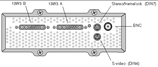
The connectors on the I/O back panel include:
- 13W3 analog video connector, marked B
- 13W3 analog video connector, marked A
- Stereo/framelock connector (7-pin micro-DIN)
- S-video connector (4-pin micro-DIN)
- Genlock In BNC connector
FIGURE F-1 shows the connector locations on the board back panel.
FIGURE F-1 Sun XVR-4000 Graphics Accelerator Back Panel I/O Ports
 [ D ]
[ D ]
Pinout for the 13W3 Connector
FIGURE F-2 and TABLE F-2 shows the Sun XVR-4000 graphics accelerator 13W3 connector and lists the pinout signals.
FIGURE F-2 Sun XVR-4000 Graphics Accelerator Back Panel 13W3 Connector

TABLE F-1 Sun XVR-4000 Graphics Accelerator 13W3 Connector Pinout
|
Pin Number
|
Signal
|
Description
|
|
1
|
I2C_SCL
|
Clock input for DDC1/2B
|
|
2
|
DDC_+5V
|
+5V from DDC frame buffer
|
|
3
|
Unused
|
|
|
4
|
Ground
|
Ground return for serial data (pins 1 and 5) (not ground on monitor)
|
|
5
|
H/CSYNC
|
Combined H/V sync, TTL twisted pair (see pin 10), terminated by 75  resister. resister.
|
|
6
|
I2C_SDA
|
Bi-directional DDC serial data line
|
|
7
|
VSYNC
|
Vsync
|
|
8
|
Unused
|
|
|
9
|
Unused
|
|
|
10
|
Ground
|
H/Csync return (return for pin 5)
|
|
Blue
|
Blue
|
75  coax receptacle coax receptacle
|
|
Green
|
Green
|
75  coax receptacle coax receptacle
|
|
Red
|
Red
|
75  coax receptacle coax receptacle
|
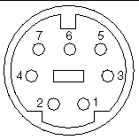
Pinout for Stereo/Framelock DIN7 Connector
FIGURE F-3 and TABLE F-2 show the Sun XVR-4000 graphics accelerator stereo/framelock DIN7 connector and pinout signals.
FIGURE F-3 Sun XVR-4000 Graphics Accelerator Back Panel Stereo/Framelock DIN7 Connector

TABLE F-2 Sun XVR-4000 Graphics Accelerator Stereo/Framelock Connector Pinout
|
Pin Number
|
Signal
|
|
1
|
Ground
|
|
2
|
Ground
|
|
3
|
STEREO_PWR (see Note)
|
|
4
|
STEREO_SYNC
|
|
5
|
FIELD_IN
|
|
6
|
DRAWING_L
|
|
7
|
FRAME_OUT
|
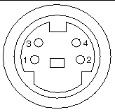
Pinout for S-Video Connector
FIGURE F-4 and TABLE F-3 show the Sun XVR-4000 graphics accelerator S-video connector and pinout signals.
FIGURE F-4 Sun XVR-4000 Graphics Accelerator Back Panel S-Video Connector

TABLE F-3 Sun XVR-4000 Graphics Accelerator S-Video Connector Pinout
|
Pin Number
|
Signal
|
Description
|
|
1
|
Y_GROUND
|
Twisted-pair return for Y signal (pin 3)
|
|
2
|
C_GROUND
|
Twisted-pair return for C signal (pin 4)
|
|
3
|
Luminance Y signal
|
Twisted pair
|
|
4
|
Chrominance C signal
|
Twisted pair
|
|
Shell
|
Chassis ground
|
|
Pinout for Genlock BNC Connector
FIGURE F-5 and TABLE F-4 show the Sun XVR-4000 graphics accelerator BNC connector and pinout signals.
FIGURE F-5 Sun XVR-4000 Graphics Accelerator Back Panel BNC Connector

TABLE F-4 Sun XVR-4000 Graphics Accelerator BNC Connector Pinout
|
Pin Number
|
Signal
|
Description
|
|
Center pin
|
GENLOCK_IN
|
75  genlock input video (RS- 170 sync source), or 4V TTL () level. genlock input video (RS- 170 sync source), or 4V TTL () level.
|
|
Shell
|
GENLOCK_RETURN
|
Nominally ground. The ground is not directly connected to the Sun XVR-4000 graphics accelerator chassis or logic ground. You may ground at external equipment.
|
 [ D ]
[ D ]


