| C H A P T E R 2 |
|
Configuring the RFID Event Manager |
This chapter includes the following topics:
The RFID Event Manager consists of a Control Station and one or more Execution Agents as described in Chapter 1. Each Execution Agent is composed of an adapter passing information into one or more filters or connectors. The filters, in turn, can pass information into one or more connectors. This chain of processes constitutes a federation of services, known as Business Processing Semantics (BPS), where each of the services may contain one or more components linked together to process events. With the addition of the RFID Configuration Manager, the implementation of a BPS is done by creating a Configuration Object. The term Configuration Object replaces the term BPS.
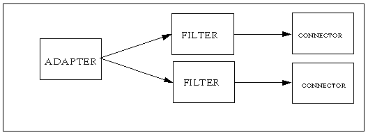
An RFID Reader is a separate piece of hardware that communicates with RFID tags over a microwave Radio Frequency. The RFID Reader communicates with an adapter through a proprietary protocol. The reader adapter is a driver-like piece of Java code that interfaces to the actual RFID Reader device. The supported adapters are listed in TABLE 2-3. Device Profiles for the supported adapters are provided with this software.
The adapter functions by receiving the EPC of the RFID tag and generating an event that includes a timestamp and the source of the event - the reader and antenna that read the tag. The event is posted to a set of listeners, such as filters or connectors, that then process the event.
Filters can smooth the data, throw away previously detected information, or route information to other filters and connectors based on mask matching. The filtered data is posted as an event to defined listeners. The listeners can be other filters that further process the data or connectors that serve as connectors to third-party applications that use the RFID information. This collection of adapters, filters and connectors is known as a Role.
At installation time, you specified a unique Jini Group to use in your RFID environment. The RFID Configuration Manager Deployment Parameters dialog enables you to change the value of this Jini Group. This dialog is also used to define the IP address, the port number and directory of the web server (by default, the web server is Rio Webster) serving the Java classes to the Execution Agents. The Execution Agents receive their workload dynamically at startup, and obtain the Java classes required to execute the workload from this web server. This web server is configured at install time to use port 52493.
The current system values are displayed when the user invokes this dialog.
1. Start the RFID Configuration Manager.
See To Start the Configuration Manager.
2. Choose File  Deployment Parameters.
The Deployment Parameters dialog is displayed.
3. Review or change the parameters as necessary.
You are discouraged from changing these parameters except in the following situations:
|
Caution - Exercise extreme caution when updating these parameters, as the system may become unusable if the incorrect parameters are used. |
In the first release of this software, the configuration of the BPS for an Execution Agent was accomplished by editing the XML configuration file for each Execution Agent. This release of the software provides a configuration tool, the RFID Configuration Manager, to simplify this task. You no longer have to edit raw XML files to define the attributes of the RFID readers or to define the Business Processing Semantics (BPS). You can now use the RFID Configuration Manager tool to define a Configuration Object.
|
Note - See the appendixes for information on configuring the Event Manager by editing the XML configuration file. Appendix A contains information for the supported adapters. Appendix B contains information for the supported components (filters and connectors). Appendix C has sample XML files. |
The RFID Configuration Manager consists of a configuration service and a user interface to the service. To begin using the Configuration Manager, it is necessary to understand the concepts of Device Profiles, RFID components, Roles, Configuration Objects, and Devices.
See Managing Event Manager Components for more details on the components provided with the RFID Software
For example, consider the case where you create two roles, 1=DockDoor and 2= ConveyorBelt. You can use these Roles to create multiple Configuration Objects depending on the location and functionality of the associated physical reader, such as:
One Configuration Object might indicate inbound and one outbound through the dock door depending on the property settings of the physical readers associated with the Configuration Object.
The RFID Configuration Manager is the tool used to create and manage the Components, Profiles, Roles, Devices and Configuration Objects. The next section contains procedures describing how to use this tool.
The RFID Configuration Manager interface is composed of the following elements:
When the RFID Configuration Manager is started, it reads four data stores (persistent descriptions of structures). These data stores contain descriptions of Roles, Device Profiles and Components, and are located in the default install_dir of the RFID Event Manager.
|
Note - Do not hand edit these files, as they are dynamically generated by the Configuration Manager: |
Use the RFID Configuration Manager for the following configuration tasks:
A predefined set of Device Profiles and RFID Event Manager Components are included with the software. These are necessary building blocks for configuring the RFID Software system. You can also specify new Device Profiles and Components.
The basic steps for configuring your RFID Event Manager are shown in TABLE 2-2.
|
1. If you have not installed the RFID Event Manager, see the Sun Java System RFID Software 2.0 Installation Guide. You need to use the RFID Configuration Manager tool on the machine where the RFID Event Manager Control Station is installed because the RFID Configuration Manager needs access to the file system on that machine.
After you have successfully completed the installation, proceed to Step 2.
2. Enable access to the X server.
4. Set the DISPLAY environment variable to display to your machine name. For example, using the csh:
5. From the command line, execute the start script. For example, on Solaris OS using the default install_dir:
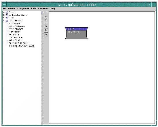
You see something similar to the following (the nodes in the navigation tree on the left may be expanded):
6. (Optional) Expand the Device Profiles node to see the supported Device Profiles that have been installed with your RFID Event Manager.
|
A Device instance is a physical instance of a Device Profile in the RFID system. A physical device must have a defining Device Profile associated with it. All device instances are defined by their Device Profiles, IP addresses and IP ports. The Device Profile and IP address must be defined. The IP port is optional.
1. From the RFID Configuration Manager menu, choose Devices  New.
New.
The Reader Properties dialog is displayed.
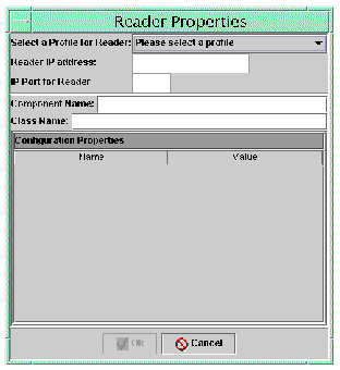
2. Click `Please select a profile' to see a drop-down list of possible Device Profiles. All other fields are null until you select the base profile.
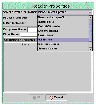
3. Select the profile from the drop-down list.
The default properties associated with this profile are loaded into the dialog.
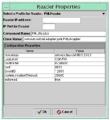
4. Type the Reader IP address and the IP Port and press Enter.
Use the Reader IP address and IP Port for an actual physical reader in your RFID system. This function ties the physical reader to the proper Device Profile.
5. (Optional) Change the property values if needed. When finished click Ok.
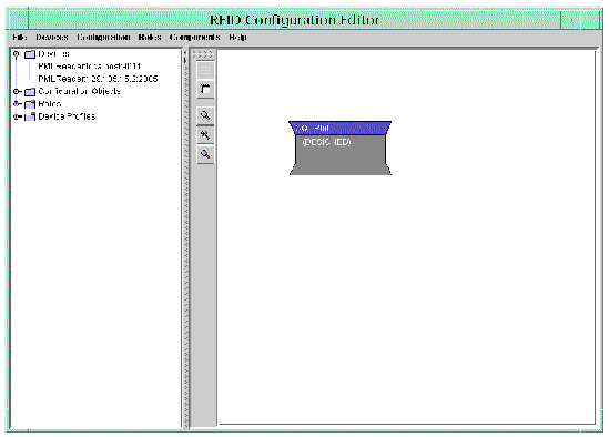
The newly created Device instance is displayed in the navigation tree. For example, the following screen capture shows a new PMLReader with IP address of 129.135.15.2 and a IP Port of 2005.
|
Use the drawing pane of the RFID Configuration Manager to visually create the Roles that comprise your RFID application.
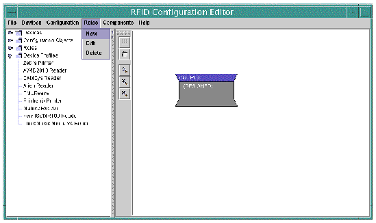

2. Type the name of the Role and click Ok.
Use a descriptive name for the role. The drawing pane is prepared to create the new Role in the Role and Component Editor. The new Role name appears in the navigation tree on the left of the designer under the Roles node.
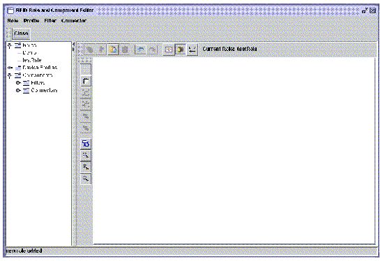
3. Place the components on the drawing pane.
Use the icons on the toolbar to add filters and connectors. When you click one of the component icons, you see a drop-down list of the available components of that type. Select one, type a unique name, and press Ok to add it to the drawing pane. For example, add the Smoothing Filter.
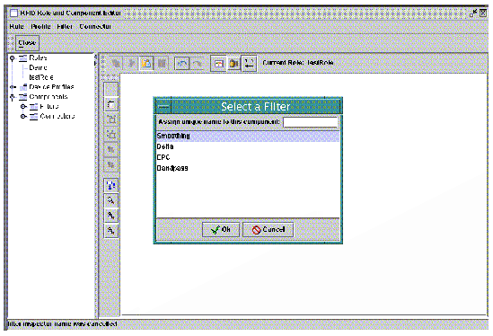
4. After adding a filter, it appears on the drawing pane. The following screen capture shows the drawing pane after adding the Smoothing Filter and a connector.
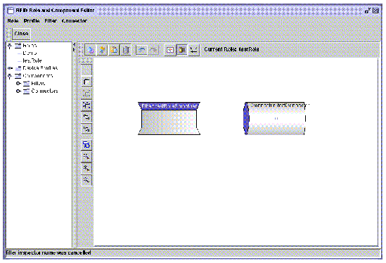
5. Connect the Components in the necessary order.
This is done by clicking the port (the small square at the center of each component) and dragging a line to another component. This act connects the output of one component to the input of another component. Filters connect to connectors and to other filters. Do not connect a connector to another connector, this has no meaning in the RFID system configuration. The following screen capture shows the Smoothing Filter connected to the testConnector.
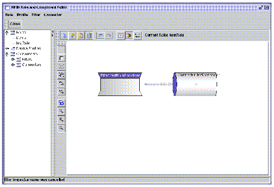
6. Now, add an input point to the Role.
The input point for the role is the attachment point by which a physical device provides data to the role in a real configuration instance. You must define an input point for the Role.
a. Click the input icon. This is the icon with the two arrows pointing opposite directions. Place the cursor over the icons to see a description of its function.
A dialog showing the available input points is displayed. The input points that you see in the dialog are the components that you have added to this role. Typically, the input point is a filter.
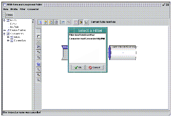
b. Select the input point and click Ok to add it to the role. The input is displayed on the drawing pane.
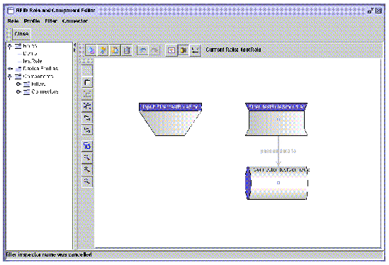
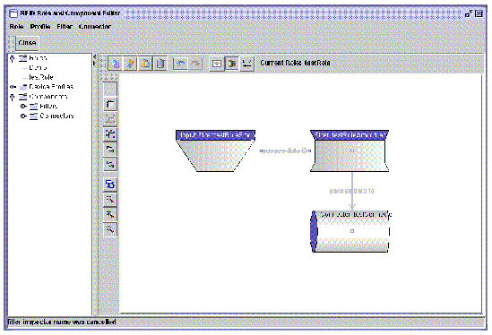
c. Connect the input point to the proper component.
Once you have added the necessary filters, connectors, an input and connected everything as needed, the Role is ready to save. The following screen capture shows a completed role with one filter, one connector and the filter designated as the input point feeding the input data to the connector.
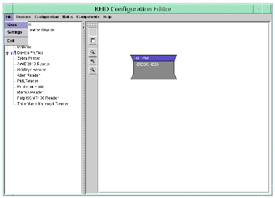
7. To save the role, return to the RFID Configuration Editor and from the main menu, choose File  Save.
Save.
This function is used to save all work done with the Configuration Manager. You can not save your work from the Role and Component Editor.
|
Configuration Objects are the active entities within the RFID system. They represent the union of the physical hardware and the software functionality components that interact within an RFID implementation. When you have defined your physical readers as Devices and have created the Roles for your RFID system, you are ready to complete the configuration process by defining the Configuration Objects.
1. From the RFID Configuration Manager menu, choose Configuration  New.
New.
A dialog appears that lists the available Roles.
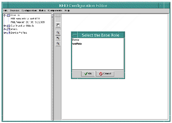
2. Select the role on which to base this Configuration Object and click Ok.
The Configuration Object dialog is displayed.
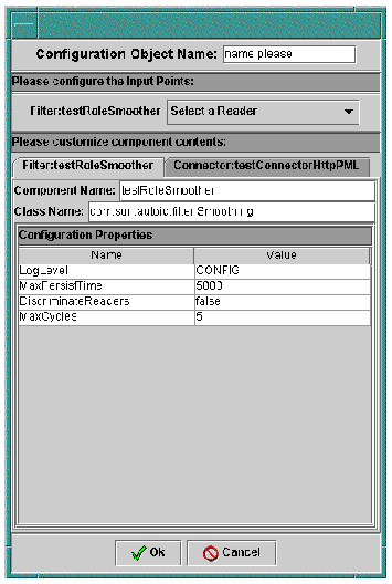
3. The dialog has four areas for input:
You can change component properties of the role to satisfy unique constraints of your system. The following screen capture shows the testRole and Device that were defined in the prior procedures with the list of defined Devices expanded.
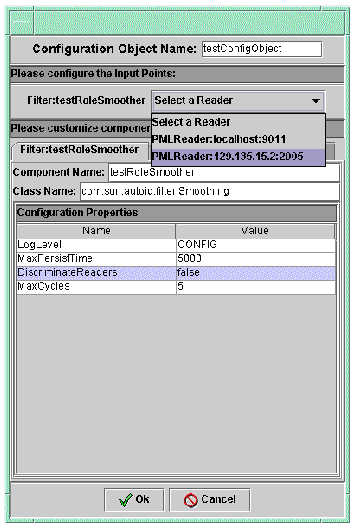
4. Type a name for your Configuration Object and select a reader to add that reader component property set to the Configuration Object and propagate the appropriate interconnections.
A tab is added for the selected reader. Click the tab to show the reader properties. This is where you can make changes to the specific values for this Configuration Object. For example, you can change the maximum number of cycles that defines the communicationTimeout for the reader.
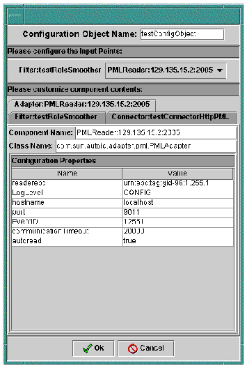
5. When you have finished customizing the Component properties, click Ok to create the Configuration Object.
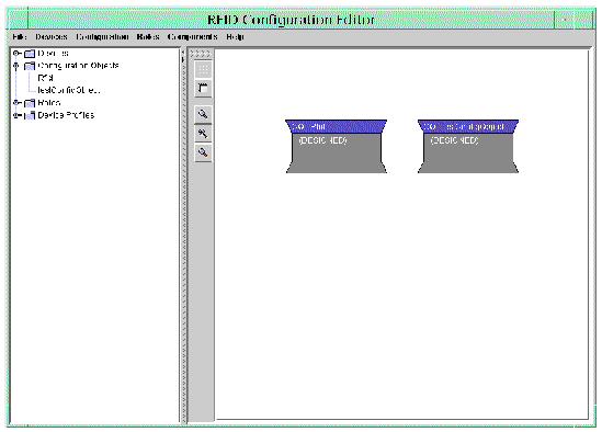
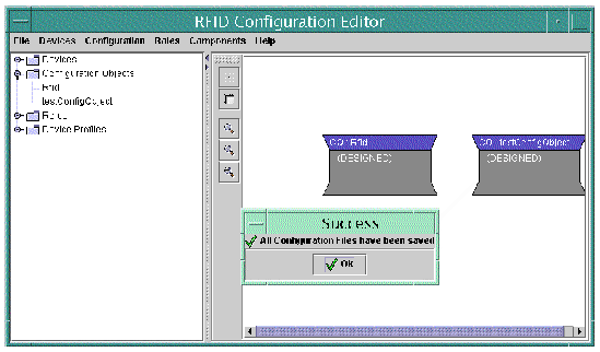
The Configuration Object is placed on the drawing pane of the RFID Configuration Manager and also appears in the navigation tree under the Configuration Objects node. The following screen capture shows the testConfigObject created in the prior procedures.
6. Save your work by choosing File  Save from the RFID Configuration Manager main menu.
|
1. From the RFID Configuration Manager menu, choose Configuration  Edit.
Edit.
2. Select the Configuration Object to edit.
You are prompted to indicate whether, you want to change the readers assigned to this Configuration Object.
|
When you have completed the definition of your RFID system's Configuration Objects, you must stop and restart the RFID Event Manager if it was already running. If it was not running, start it.
1. After you install Event Manager, change to the install directory containing the start script:
2. Execute the script to start all the components of the Event Manager.
|
Note - Refer to the Sun Java System RFID Software 2.0 Installation Guide for more information on installed scripts and directories associated with this software. |
The RFID Software comes with a predefined set of Device Profiles that describe the supported device adapters. The adapters understand the specific communication protocol used by the leading EPC-compliant RFID readers and devices such as printers. These device adapters can be viewed as equivalent to device drivers used to communicate with peripherals in a computer system. Each adapter implements vendor-specific communication protocols to communicate with that vendor's RFID device.
The Device Profiles describe the set of properties and their values for the device adapters. When you start the RFID Configuration Manager, you have access to these Device Profiles. You can modify the default settings and use the Device Profiles to create the Configuration Objects needed by your RFID system.
The RFID Configuration Manager provides the following functions for managing RFID Device Profiles:
Device Profiles implement adapters with a particular set of property values. Adapters gather RFID events from readers and propagate the events to other components as defined by the Role. For this software release, the RFID Event Manager supports devices through the use of the adapters described in TABLE 2-3.
An Adapter is defined by the following:
Device-specific properties and additional considerations for the common properties are described in the device-specific tables listed in the Configuration Description column of TABLE 2-3.
Device Profiles for the readers and other devices listed in TABLE 2-3 are preloaded in the RFID Configuration Manager. You can modify the default settings by using the RFID Configuration Manager tool that is described in section Using the RFID Configuration Manager.
|
See TABLE A-1 |
||
|
See TABLE A-2 |
||
|
See TABLE A-7 |
||
|
ThingMagic Mercury3 RFID Reader SensorMatic SensorID Agile 1 Reader |
See TABLE A-5 |
|
|
ThingMagic Mercury4 RFID Reader SensorMatic SensorID Agile 2 Reader |
See TABLE A-6 |
|
|
See TABLE A-4 |
||
|
See TABLE A-3 |
||
|
See TABLE A-8 |
||
|
See TABLE A-9 |
||
|
See TABLE A-10 |
All Device Adapters support a basic set of properties, unless otherwise specified in the configuration section of the Adapter. The common properties are described in TABLE 2-4.
1. Log Level - Log level settings follow logging conventions established in J2SE, version 1.4.2. See the API documentation for the class java.util.logging.Level found at http://java.sun.com/j2se/1.4.2/docs/api/index.html for more information. Also see "Log Files" in the Sun Java System RFID Software Installation Guide.
2. Reader EPC Identifier - This property, readerepc, is the EPC value associated with the reader. This property is used by the RFID Event Manager to identify the source of the events. Values other than the one shown in TABLE 2-4 are possible. Refer to the EPC specification for further customization information.
3. Autoread Capability - Some RFID readers can be configured to continuously report RFID tag events in their field, without requiring the adapter to constantly ask for them. When autoread is enabled, the adapter configures the RFID reader into automatic read mode and goes into a listening mode. In turn, the adapter reports the list of tags to its consumers. The PMLReader supports autoread mode.
When autoread is enabled, the adapter instructs the reader to do the following:
When the RFID reader does not support automatic mode and autoread has been enabled, the adapter loops generating requests to the reader to obtain the list of tags. This generates extra network traffic, as there needs to be a request for every response, instead of simply listening for reports without asking for them.
When autoread is disabled, the consumers of the reader adapter do not see tag events unless an external software module initiates the tag list request programmatically. The autoread property is disabled by default.
|
1. From the RFID Configuration Manager main menu, choose Components  Device Profiles.
The RFID Role and Component Editor is displayed with the Device Profile node expanded.
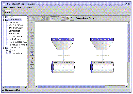
2. From the RFID Role and Component Editor main menu, choose Profile  Edit.
Edit.
The Device Profile Selection dialog is displayed.
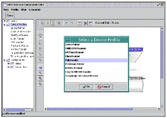
3. Select the Device Profile to edit and click Ok.
The Profile Inspector dialog is displayed.
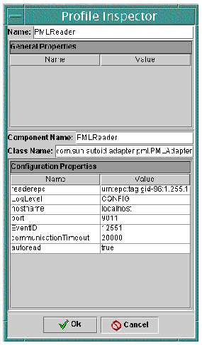
The first value is the Profile Name, which identifies the profile uniquely.
The next area of the dialog shows the configuration properties. See Appendix A for detailed descriptions of these properties for each of the supported adapters.
4. Type the new values and click Ok when your entries are completed.
Your work is only saved to an in-memory database at this point. You must save the results of your changes explicitly as described in the next step.
5. Return to the RFID Configuration Manager interface and choose File  Save.
Save.
The primary types of Components are filters and connectors.
Zero or more filters may be defined. Filters are linked from input events to other components that name them as outputs. The following attributes define a filter:
The filters supported in this release are listed in TABLE 2-5. For a description of the filter's associated properties, click on the link in the Properties column.
Zero or more connectors may be defined. Connectors are linked for input events to other components that name them as outputs. A connector is defined by the following attributes:
The connectors supported in this release are described in TABLE 2-6. For a description of the connector's associated properties, click on the link in the Properties column.
|
Performs a pass filter on the reader EPCs. Events from readers that match the EPC Mask are passed on to listeners, while others are not. |
See TABLE B-4 |
|
|
See TABLE B-2 |
||
|
Performs a pass filter on tag EPCs. EPCs that match the EPC Mask are passed on to listeners, while others are not. |
See TABLE B-3 |
|
|
Creates a union of EPCs discovered over the number of specified n cycles. If an EPC was discovered in cycle < n, it is reported, if it hasn't been seen in more than the last n cycles, it is not reported. This is necessary because the RFID readers do not report tags with 100% tag accuracy. |
See TABLE B-1 |
|
See TABLE B-5 |
||
|
See TABLE B-6 |
||
|
See TABLE B-7 |
||
|
Creates a Socket connection and starts writing PML Core to the connection |
See TABLE B-8 |
|
|
Creates a Server Socket and listens for a connection. It starts writing PML Core once the connection is established. |
See TABLE B-9 |
Copyright © 2004, Sun Microsystems, Inc. All Rights Reserved.