Appendix D Rules for System Configuration
Some of the following rules are suggestions for optimizing your system. Other rules are required or maximum values and are marked with the notation Requirement or Maximum.
Card Cage
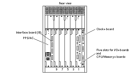
In the card cage (see Figure D-1), board slots are numbered from right to left: 1, 3, 5, 7, and 9.
Note -
This seemingly unconventional numbering system is derived from the slot numbering used in the general card cage design of the Enterprise server family. The Enterprise 3500 server card cage is based on the Enterprise 4500 card cage, which is double-sided, with even-numbered slots (0, 2, 4, 6) on the front and odd-numbered slots (1, 3, 5, 7) on the back. The Enterprise 3500 card cage uses the system internal SCSI bus (slot 1), which in turn dictated the use of the back half of the Enterprise 4500 card cage design
In most respects, all five board slots in the card cage are equivalent. However, slot 1 is the only slot that is physically connected in the card cage to the SCSI bus on the centerplane. Slot 1 is therefore normally reserved for an I/O+ board, since the CPU/Memory+ board does not have a SCSI bus controller.
I/O+ Boards
-
Requirement - Reserve slot 1 for an I/O+ board (see Figure D-1). This is the only slot that allows direct access to the internal SCSI devices.
-
Maximum - Up to four graphics (UPA) cards are supported in a system.
-
Requirement - The SCSI bus on the I/O+ board in slot 1 must be terminated because it connects to the internal system SCSI bus.
-
An I/O+ board in a slot other than slot 1 does not require termination if no devices connect to the SCSI bus on that board.
Figure D-1 Board Slots and AC Power Supply

Interface Board
-
There is a slot for one Interface Board (IB) in the system (see Figure D-1). The IB provides circuitry for disk drives using fibre channel arbitration loop (FC-AL) interfacing.
-
The system can have up to eight internal fiber optic disk drives, which are controlled by Gigabit Interface Converters (GBICs) mounted on the IB. The GBICs are hot-pluggable. The GBICs on the IB connect by cables to GBICs on the I/O+ board(s).
-
The IB has Fibre Channel-Arbitrated Loop (FC-AL) circuitry to support up to eight internal fiber optic disk drives. Two GBICs (in slots LA and UA) on the IB connect through cables to GBICs on the I/O+ board. The remaining GBIC slots (LB and UB) on the IB can be used for redundant interfacing to another I/O+ board or (with the proper software) to an entirely separate system.
-
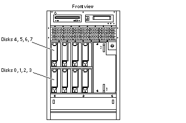
One GBIC can control up to four fiber optic disk drives (disk bays 0 to 3 in the lower bank, or bays 4 to 7 in the upper bank). Reserve bay 0 for the boot drive.
-
There are two FC-AL loops for the internal disk drives. The lower loop connects disks 0 to 3 (lower disk bays); the upper loop connects disks 4 to 7 (upper disk bays).
CPU/Memory+ Boards
-
When configured at the factory, a CPU/Memory+ board is installed in the second slot (slot 3) of the five board slots (see Figure D-1.) As noted earlier, slot 1 is reserved for an I/O+ board.
-
Maximum - The Enterprise 3500 server supports up to four CPU/Memory+ boards.
Power Supplies and Fan Cooling
-
Requirement - The slot directly above a CPU/Memory+ board or I/O+ board must contain a power/cooling module (PCM), because the fans in the PCM are the only source of cooling air for the board slot.
-
Requirement - All unused slots must contain a filler panel to avoid loss of cooling air.
-
Under some circumstances, you can remove a PCM from an active system for a short time. However, if the boards in the adjacent slots create large quantities of heat, it is safer to halt and power off the system first.
-
Requirement - The peripheral power supply/AC input (PPS/AC) must be fully functional if you replace a hot-pluggable board or PCM. (Only the PPS/AC provides precharge current to the system. If the PPS/AC cannot supply precharge current, the hot-pluggable module will be damaged.)
-
Requirement - The slot above the PPS/AC must contain either a PCM or an auxiliary fan tray.
-
The auxiliary peripheral power supply (PPS 1) is an option. The PPS 1 is located at the front of the system, to the right of the disk drive area.
-
Requirement - If PPS 1 is absent, the slot must contain a thermal protection module to ensure the maximum operating temperature is not exceeded.
-
PPS 1 does not provide precharge current.
Filler Panels
-
Requirement - Board filler panels are required for all unused board slots.
-
Requirement - PCM filler panels are required for all unused PCM bays.
-
Requirement - A thermal protection module must be installed if an auxiliary peripheral power supply (PPS1) is not installed.
SBus Cards
-
Install double-wide SBus cards only on the SBus+ I/O board in SBus slots 1 and 2. The location of SBus slot 0 prevents its use with double-wide cards.
-
Double-wide SBus cards cannot be used with the Graphics+ I/O board. The middle card connector does not fit SBus cards.
CPU Modules
-
Each CPU/Memory+ board has two sets of CPU connectors, marked PROC 0 and PROC 1.
-
Do not mix CPU speeds.
-
The order in which you fill CPU slots is not critical. However, to optimize heat dissipation in the system:
-
Fill all PROC 0 locations on all CPU/Memory+ boards before filling any PROC 1 locations. To receive the maximum quantity of diagnostic information, fill PROC 0 on board 3.
-
After all PROC 0 locations are filled, you can begin filling the PROC 1 locations, again starting from the lowest slot number to the highest.
Table D-1 shows slot locations for an example of five CPUs on three CPU/Memory+ boards.
|
Slot Number |
PROC 0 |
PROC 1 |
|---|---|---|
|
3 |
in |
in |
|
5 |
in |
in |
|
7 |
in |
|
Memory Modules
-
The SIMMs are 168-pin, JEDEC-standard devices. Do not use other types of memory modules.
-
Requirement - Do not mix 8, 32, or 128 Mbyte SIMMs in the same bank. (All SIMMs in a bank -- eight SIMMs -- must have the same capacity.)
-
Note that two banks of SIMM slots on a CPU/Memory+ board are interleaved. A bank is composed of eight alternating SIMM slots.
-
All SIMMs in a bank should have the same speed rating. If SIMMs of different speeds are mixed in a bank, the bank will function, but at the lowest speed.
Cabling
SCSI
-
Requirement - Do not attach any external SCSI devices to the onboard SCSI connector of the I/O+ board in card cage slot 1.
-
To add external SCSI devices, use the SBus slots on the I/O+ board, or add a second I/O+ board. You may use either an SBus+ I/O board or a Graphics+ I/O board.
-
Maximum - The maximum length for a chain of single-ended (non-differential) SCSI cables is 6.0 meters (20 feet).
-
Maximum - The maximum length for a chain of differential SCSI cables is 25 meters (82 feet).
Fiber Optic
The minimum bend radius for fiber optic cable is 1.0 inch. The IB has Fibre Channel- Arbitrated Loop (FC-AL) circuitry to support up to eight internal fiber optic disk drives. Two GBICs (in slots LA and UA) on the IB connect through cables to GBICs on the I/O+ board; use a 2-meter cable. The remaining GBIC slots (LB and UB) on the IB can be used for redundant interfacing to another I/O+ board or (with the proper software) to an entirely separate system. Use the fiber cable organizer that came with your E3500 system to help ensure the 1.0 inch bend radius rule is observed.
Ethernet
-
The main Ethernet should be connected to the I/O+ board in slot 1.
-
Each I/O+ board has one Ethernet circuit with both TPE and MII connectors. Only one type of connector may be used at a time.
-
After slot 1 is connected to a network, additional Ethernet connections may be made to I/O+ boards or SBus cards in any other card cage slot.
Video Interface
-
A system that is operated with a monitor can use a graphics adapter mounted on either a Graphics+ I/O board or an SBus+ I/O board.
-
Up to four Graphics+ I/O boards are supported in a system.
CD-ROM/Tape Drive Media Tray
The media tray is located at the upper front of the cabinet. Various CD-ROM and tape drive options are available. A SCSI cable connects the tray to card cage slot 1 on the centerplane.
Disk Drives
Disk drive bays are located at the front of the cabinet.
In the lower bank of disk drives, the bay numbers are 0, 1, 2, and 3, numbered from left to right. See Figure D-2.
Requirement - Bay 0 is reserved for the boot disk.
In the upper bank of disk drives, the bay numbers are 4, 5, 6, and 7. See Figure D-2.
All disk drives connect through the centerplane to the interface board (IB) which provides a fiber optical interface.
Figure D-2 Disk Drive Bay Numbers

- © 2010, Oracle Corporation and/or its affiliates
