Appendix E Non-Chassis Field Replaceable Units (FRUs)
See the following pages to remove and replace system subassemblies.
FRU List
Table E-1 List of Field Replaceable Units|
FRU List Items |
Part Number |
|---|---|
|
Assembly, cable, SCSI tray data (media tray) |
530-2220 |
|
Assembly, cable, power, DC |
530-2221 |
|
Assembly, cable, key switch PWB centerplane |
530-2226 |
|
Centerplane |
501-4799 |
|
Fan tray assembly |
540-3566 |
|
Fan tray assembly, auxiliary |
540-2757 |
|
Key switch lock cable assembly |
530-2148 |
|
LED board |
501-2599 |
Fan Tray Assembly
Removing the Fan Tray Assembly
-
Pull open the front door of the Enterprise 3500 system.
-
Locate the fan tray assembly at the bottom of the system.
-
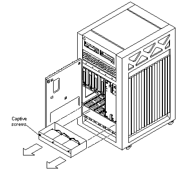
Loosen the three captive screws securing the fan tray assembly in the chassis. See Figure E-1.
Figure E-1 Removing the Fan Tray Assembly
-
Gently pull the fan tray assembly from the chassis and set it aside.
Replacing the Fan Tray Assembly
-
Carefully insert the fan tray assembly in the Enterprise 3500 system. See Figure E-1.
 Caution -
 DO NOT FORCE the fan tray assembly into the slot; this can cause damage to the fan tray assembly and system.
The fan tray assembly should insert and seat smoothly. If it binds, remove it, and inspect the slot for any obvious obstructions. Do not damage the springfingers at the bottom of the fan tray assembly.
-
Tighten the three captive screws securing the fan tray assembly to the chassis.
-
Close the front door of the Enterprise 3500 system.
Auxiliary Fan Tray Assembly
Removing the Auxiliary Fan Tray Assembly
-
Locate the auxiliary fan tray assembly at the back of the system.
Viewed from the rear of the system, the auxiliary fan tray is on the upper left side of the chassis, in PCM slot 5 (slot 5 can contain either an auxiliary fan tray or a PCM).
-
Release the auxiliary fan tray from the system chassis by inserting a Phillips #1 screwdriver into each quarter-turn access slot and turning to the unlocked position. See Figure E-2.
Figure E-2 Unlocking and Locking Quarter-Turn Access Slots

-
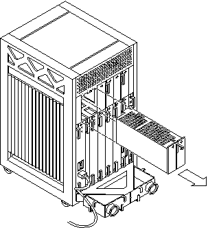
Pull the end of the extraction lever outward to release the auxiliary fan tray assembly from the centerplane. See Figure E-3.
Figure E-3 Removing the Auxiliary Fan Tray
-
Slowly remove the auxiliary fan tray assembly from the chassis and set it aside.
Replacing the Auxiliary Fan Tray Assembly
-
Carefully insert the auxiliary fan tray into the slot at the back of the Enterprise 3500 system.
-
Ensure that the extraction lever is in the outward position.
-
Orient the auxiliary fan tray with the extraction lever on the outside edge of the Enterprise 3500 system. See Figure E-3.
-
-
Slide the auxiliary fan tray assembly toward the centerplane.
The auxiliary fan tray assembly will not seat fully unless the lever is in this starting position.
 Caution -
 DO NOT FORCE the auxiliary fan tray assembly into the slot; this can cause damage to the auxiliary fan tray and system.
The auxiliary fan tray assembly should insert and seat smoothly. If it binds, remove it, and inspect the slot for any obvious obstructions. Do not damage the springfingers at the bottom of the auxiliary fan tray assembly.
-
Swing the extraction lever inward to the locked position to seat the auxiliary fan tray assembly.
Do not press on the front panel of the auxiliary fan tray assembly to seat it; doing so will damage the connector pins.
-
Lock the auxiliary fan tray to the system chassis by inserting a Phillips #1 screwdriver into each quarter-turn access slot and then turning to the locked position. See Figure E-2).
Removing the Front and Side Panels
Complete the following section as a prerequisite if you are removing one of the following subassemblies:
-
Media (SCSI) tray data and DC power cable assemblies
-
Key switch PWB centerplane cable assembly
-
Key switch lock cable assembly
-
LED board
-
Centerplane
Removing the Side Panels and Front Bezel
-
Completely power off the Enterprise 3500 system.
See the power-off instructions in Chapter 11, Powering Off and On.
-
Remove the side panels.
-
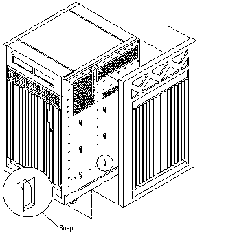
Grasp the bottom of the side panel in the center and pull the panel out slightly until the snap disengages.
-
Lift the side panel up and then lift the panel out. See Figure E-4.
Figure E-4 Removing the Side Panel
-
-
Grasp the front bezel on both sides near the center.
Place your thumbs on top of the front bezel and place your other fingers at the slight indentations under the front bezel.
-
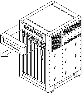
Pull the front bezel straight out toward you and set it aside.
Press down on the top of the bezel as you pull it toward you, and pull back slightly on the top with your thumbs. See Figure E-5.
Figure E-5 Removing the Front Bezel
Removing the Media Tray and Front Decorative Panel
-
Loosen the two captive screws securing the media tray in the chassis.
-
Insert a screwdriver or similar instrument in the notch at the bottom center of the media tray. Using the screwdriver, slightly pull out the media tray.
-
Grasp the media tray and gently pull it from the chassis. See Figure E-6.
Figure E-6 Removing the Media Tray
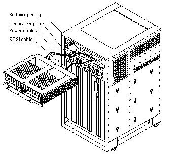
Note -If you are not replacing the SCSI cables or the centerplane, you may simply flip over the media tray and rest it on the top of the Enterprise 3500 system.
-
If you are replacing SCSI cables or the centerplane, disconnect the cables from the back of the media tray.
-
Open the front door of the Enterprise 3500 system.
-
If you are replacing the centerplane, go to "Centerplane".
-
Otherwise, continue with Step 6.
-
-
Remove the screws securing the front decorative (perforated) panel in the chassis.
There are eight screws on the top, seven screws on the bottom, and three screws on each side of the front decorative panel.
-
Grasp the front decorative panel and set it aside.
Media Tray Data and DC Power Cable Assemblies
Removing the Data and Power Cables
-
Remove the panels covering the data and power cables.
Complete the steps in "Removing the Front and Side Panels".
-
Reach through the space previously occupied by the front decorative (perforated) panel and disconnect the SCSI cables from the centerplane.
-
Cut the cable ties that secure the cables to the chassis.
-
Remove the cables.
Replacing the Data and Power Cables
-
Connect the cables to the back of the media tray.
Note -The SCSI data and power cables are keyed so that the cables fit into the connectors in only one direction and cannot be reversed.
-
Place the cables through the chassis opening vacated by the media tray. Drop the cables through the bottom opening.
The cables should be visible through the opening normally covered by the front decorative (perforated) panel. See Figure E-6.
-
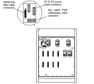
Reach through the space normally covered by the front decorative panel and connect the cables to the centerplane. See Figure E-7.
Figure E-7 Cable Connectors on the Centerplane
-
Replace the panels covering the data and power cables.
Complete the steps in "Replacing the Front and Side Panels".
Key Switch PWB Centerplane Cable Assembly
Removing the Key Switch PWB Centerplane Cable Assembly
-
Remove the panels covering the key switch printed wiring board (PWB) centerplane cable.
Complete the steps in "Removing the Front and Side Panels".
-
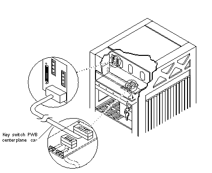
Disconnect the key switch PWB centerplane cable from the centerplane. See Figure E-8.
Figure E-8 Key Switch PWB Centerplane Cable
-
Disconnect the key switch PWB centerplane cable from the LED board.
-
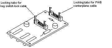
Pull forward on the two locking tabs securing the cable to the LED board.
The key switch PWB centerplane cable is in back of the key switch lock cable assembly. See Figure E-9.
Figure E-9 Locking Tabs on the LED Board
-
Disconnect the cable.
-
-
Cut the cable tie and remove the key switch PWB centerplane cable.
Replacing the Key Switch PWB Centerplane Cable Assembly
Note -
Both ends of the key switch printed wiring board (PWB) centerplane cable are keyed so that the cable fits into the connector in only one direction and cannot be reversed.
-
Connect the key switch PWB centerplane cable to the LED board.
-
Connect the cable.
The key switch PWB centerplane cable is in back of the key switch lock cable assembly. See Figure E-8.
-
Push back on the two locking tabs and secure the cable to the LED board.
The two locking tabs fit over the connector, securing the key switch PWB centerplane cable to the LED board. See Figure E-9.
-
-
Connect the other end of the cable to the centerplane.
-
Use a cable tie and secure the key switch PWB centerplane cable to the chassis.
-
Replace the panels covering the key switch lock assembly.
Complete the steps in "Replacing the Front and Side Panels".
Key Switch Lock Cable Assembly
Removing the Key Switch Lock Cable Assembly
-
Remove the panels covering the key switch lock cable assembly.
Complete the steps in "Removing the Front and Side Panels".
-
Disconnect the key switch lock cable from the LED board.
-
Pull forward on the two locking tabs securing the cable to the LED board.
The key switch lock cable is in front of the key switch PWB centerplane cable. See Figure E-7.
-
Disconnect the cable.
-
-
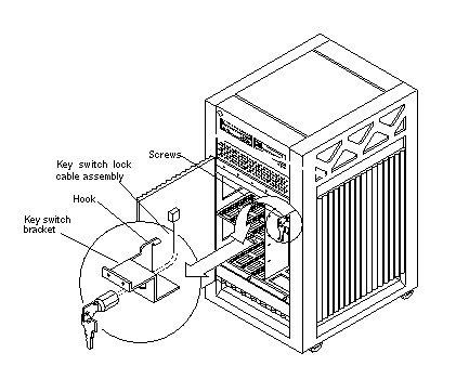
Remove the two screws that attach the key switch lock assembly to the chassis.
-
Twist the key switch lock assembly to the left and pull it forward and out away from the chassis.
The key switch lock assembly has a hook that sits on the bracket in the chassis. You need to turn the assembly so that the hook clears the bracket before the key switch lock assembly can be removed. See Figure E-10.
Figure E-10 Removing the Key Switch Lock Cable Assembly
-
Separate the key switch lock cable from the key switch bracket.
-
Remove the U-shaped key switch keeper by pulling it straight out away from the key switch lock assembly.
The key switch keeper is located on the inside of the key switch bracket and secures the cable to the bracket.
-
Remove the key switch lock cable by pulling it through the keyhole. See Figure E-10.
-
Replacing the Key Switch Lock Cable Assembly
-
Secure the key switch lock cable to the key switch bracket.
-
Insert the key switch lock cable into the keyhole of the key switch bracket.
Position the key switch lock cable so that the arrow on the front of the cable assembly is turned upward. See Figure E-10.
-
Secure the key switch lock cable to the bracket using the key switch keeper.
Slip the key switch keeper into the groove on the cable to secure the cable to the bracket.
-
-
Twist the key switch lock assembly to the left and thread it through the round hole in the right front side of the chassis.
-
Twist the key switch lock assembly to the right so that the hook rests on the bracket in the chassis. See Figure E-10.
-
Replace the two screws that attach the key switch lock assembly to the chassis.
-
Connect the key switch lock cable to the LED board.
Note -The key switch lock cable is keyed so that the cable fits into the connector in only one direction and cannot be reversed.
-
Connect the cable.
The key switch lock cable is in front of the key switch PWB centerplane cable. See Figure E-9.
-
Push back on the two locking tabs and secure the cable to the LED board.
The two locking tabs fit over the connector, securing the key switch lock cable assembly to the LED board.
-
-
Replace the panels covering the key switch lock assembly.
Complete the steps in "Replacing the Front and Side Panels".
LED Board
Note -
Use a short Phillips screwdriver to complete this procedure.
Removing the LED Board
-
Remove the panels covering the LED board.
Complete the steps in "Removing the Front and Side Panels".
-
Disconnect the key switch lock and PWB centerplane cables from the LED board. See Figure E-9.
-
Remove the four screws securing the LED board to the chassis.
There is one screw in each corner of the LED board.
-
Remove the LED board.
Replacing the LED Board
-
Orient the LED board so that the three LEDs are visible through the chassis window cutout.
-
Insert a screw into the front right corner of the LED board.
Use this screw as a guide and place the LED board against the chassis.
-
Slightly tighten the first screw and attach this corner of the LED board to the chassis.
-
Replace the three other screws that attach the LED board to the chassis.
-
Tighten all four screws.
-
Connect the key switch lock and PWB centerplane cables to the LED board. See Figure E-9.
Note -The key switch lock and PWB centerplane cables are keyed so that the cables fit into the connectors in only one direction and cannot be reversed.
-
Replace the panels covering the LED board.
Complete the steps in "Replacing the Front and Side Panels".
Centerplane
Removing the Centerplane
-
Remove the panels covering the front of the chassis.
Complete the steps in "Removing the Front and Side Panels".
-
Remove all the disk drives.
See Chapter 8, Internal SCSI and FC-AL Devices for information on removing disk drives.
-
Remove the fan tray assembly.
See "Fan Tray Assembly" for information on removing the fan tray assembly.
-
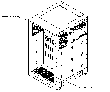
Remove the 15 screws on each side that secure the front chassis to the main chassis. See Figure E-11.
-
Remove the two screws on the top front corners that secure the front chassis to the main chassis. See Figure E-11.
-
Gently pull out the front chassis and set it aside.
-
Disconnect all the cables from the centerplane.
-
Disconnect the media tray data and DC power cable assemblies.
See "Media Tray Data and DC Power Cable Assemblies" for information on disconnecting these cables.
-
Disconnect the key switch PWB centerplane cable assembly.
See "Key Switch PWB Centerplane Cable Assembly" for information on disconnecting this cable.
Figure E-11 Enterprise 3500 System Without the Front Chassis
-
-
Disconnect all the boards from the centerplane.
See Chapter 3, CPU/Memory+ Boards and Components, Chapter 4, I/O+ Boards and Components, Chapter 5, Clock+ Board, and Chapter 6, Interface Board for information on removing the boards.
-
Disconnect the peripheral power supplies from the centerplane.
See Chapter 7, Power Supplies for information on removing the peripheral power supplies.
-
Disconnect the PCMs from the centerplane.
See Chapter 7, Power Supplies for information on removing the PCMs.
-
If present, disconnect the auxiliary fan tray from the centerplane.
See "Auxiliary Fan Tray Assembly" for information on removing the auxiliary fan tray.
-
If present, disconnect all the filler panels from the centerplane.
-
Use a Phillips #1 screwdriver to turn the arrows in the quarter-turn access slots on the filler panels to the unlocked position. See Figure E-2.
-
Pull out and disengage the filler panels from the centerplane.
-
-
From the front of the system, remove the 24 screws that secure the centerplane to the main chassis.
-
Remove the centerplane.
Replacing the Centerplane
-
Replace the 24 screws to secure the centerplane to the main chassis.
-
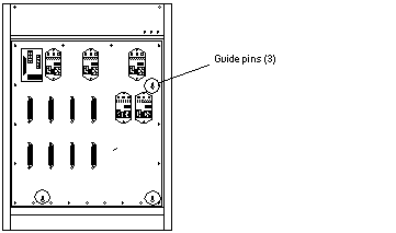
Replace and secure the front chassis to the centerplane.
Use the three guide pins to align the front chassis with the centerplane.
Figure E-12 Centerplane Guide Pins
-
Replace the two screws on the top front corners that secure the front chassis to the main chassis. See Figure E-11.
-
Replace the 15 screws on each side that secure the front chassis to the main chassis. See Figure E-11.
-
Connect all the cables to the centerplane.
-
Connect the key switch PWB centerplane cable assembly.
See "Key Switch PWB Centerplane Cable Assembly" for information on connecting this cable.
-
Connect the media tray data and DC power cable assemblies.
See "Media Tray Data and DC Power Cable Assemblies" for information on connecting these cables.
-
-
If present, connect the auxiliary fan tray to the centerplane.
See "Auxiliary Fan Tray Assembly" for information on replacing the auxiliary fan tray.
-
Connect the PCMs to the centerplane.
See Chapter 7, Power Supplies for information on replacing the PCMs.
-
Connect the peripheral power supplies to the centerplane.
See Chapter 7, Power Supplies for information on replacing the peripheral power supplies.
-
Connect all the boards to the centerplane.
See Chapter 3, CPU/Memory+ Boards and Components, Chapter 4, I/O+ Boards and Components, Chapter 5, Clock+ Board, and Chapter 6, Interface Board for information on replacing the boards.
-
Replace all the filler panels.
-
Slide the filler panels toward the centerplane.
Ensure that the arrows in the quarter-turn access slots point to the unlocked position.
The filler panel should insert and seat smoothly. If it binds, remove it, and inspect the slot for any obvious obstructions.
-
Use a Phillips #1 screwdriver to turn the arrows in the quarter-turn access slots to the locked position. See Figure E-2.
-
-
Replace all the disk drives.
See Chapter 8, Internal SCSI and FC-AL Devices for information on replacing the disk drives.
-
Replace the fan tray assembly.
See "Fan Tray Assembly" for information on replacing the fan tray assembly.
-
Replace the panels covering the front of the chassis.
Complete the steps in Appendix E, Non-Chassis Field Replaceable Units (FRUs).
Replacing the Front and Side Panels
Replacing the Media Tray and Front Decorative Panel
-
Replace the front decorative (perforated) panel.
There are eight screws on the top, seven screws on the bottom, and three screws on each side of the front decorative panel.
-
Close the front door of the Enterprise 3500 system.
-
If necessary, connect the SCSI cables to the back of the media tray.
-
Replace the media tray into the chassis opening at the front of the system.
-
Tighten the two captive screws securing the media tray in the chassis.
Replacing the Front Bezel and Side Panels
-
Place the front bezel against the chassis.
Press the panel into place. See Figure E-5.
-
Replace the side panels.
-
Place the side panel alongside the chassis
The top edge of the side panel should be approximately 1 inch higher than the chassis.
-
Slide the side panel down until it snaps into place. See Figure E-4.
-
-
Power on the Enterprise 3500 system.
See the power-on instructions in Chapter 11, Powering Off and On.
- © 2010, Oracle Corporation and/or its affiliates
