Appendix F Illustrated Parts Breakdown
The illustrations and tables in this appendix are intended to supplement the removal and replacement procedures described in previous chapters and appendixes.
Finding Part Numbers
Note -
Part numbers in this section may differ from those found in your system. Before ordering replacement parts, find the label on the part to be replaced and place your order using that number. Be sure to use the right part number (for the entire assembly instead of the individual components) as shown in Table F-1.
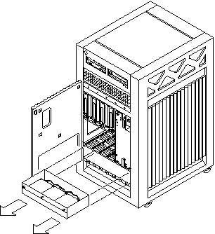
For example, the part number for the fan tray assembly is 540-3566. Although the individual fans in the assembly may have a separate part number, the part number you should use when placing your order is 540-3566 for the entire assembly.
Note -
For information about additional capacity drives and other replacement options, contact your sales representative.
List of Illustrations
Table F-1 List of Replaceable Components|
General Category |
Description |
Part Number |
|---|---|---|
|
Fan tray |
Fan tray assembly |
540-3566 |
|
|
Fan tray assembly, auxiliary |
540-2757 |
|
|
Centerplane assembly |
501-4799 |
|
SCSI and FC-AL devices |
Disk drive |
540-3249 |
|
|
Fiber optic cable assembly, 2-meter |
537-1004 |
|
|
Terminator, 68-pin |
150-2267 |
|
|
Sun CD |
370-3416 |
|
|
4/8 Gbyte 4 mm tape drive |
370-2177 |
|
|
2.5 Gbyte QIC tape |
370-2202 |
|
|
Media (SCSI) tray data cable assembly |
530-2220 |
|
|
SCSI DC power cable assembly |
530-2221 |
|
|
Key switch lock cable assembly |
530-2148 |
|
|
Key switch tray, LED board |
501-2599 |
|
|
Key switch PWB centerplane cable assembly |
530-2226 |
|
Power |
Power supply, peripheral (auxiliary) |
300-1358 |
|
|
Power supply, peripheral with AC input |
300-1400 |
|
|
Power/cooling module (PCM) |
300-1260 |
|
|
PCM filler panel |
540-2593 |
|
|
Thermal protection module |
540-3815 |
|
Boards |
CPU/Memory+ board assembly |
501-4882 |
|
|
4 Mbyte, 250 MHz CPU module |
501-2976 |
|
|
4 Mbyte, 336MHz CPU module |
501-4363 |
|
|
Assembly, DRAM, 1MX72, JEDEC, SIMM, 60 ns |
501-2652 |
|
|
Assembly, DRAM, 4MX72, JEDEC, SIMM, 60 ns |
501-2653 |
|
|
Assembly, DRAM, 16MX72, JEDEC, SIMM, 60 ns |
501-2654 |
|
|
SBus+ I/O board assembly |
501-4883 |
|
|
Graphics+ I/O board assembly |
501-4884 |
|
|
PCI+ I/O board |
501-4926 |
|
|
Optical link card |
370-2303 |
|
|
DFB, FFB Graphics Card, 67 MHz |
501-4126 |
|
|
SFB, FFB Graphics Card, 67 MHz |
501-4127 |
|
|
Clock+ board assembly |
501-4946 |
|
|
Centerplane |
501-4799 |
|
|
Board, filler panel |
540-2592 |
|
|
Interface board |
501-4820 |
|
|
Interface board, filler panel |
540-3795 |
Illustrations
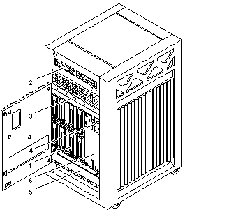
Figure F-1 Front View
|
Key |
Description |
Part Number |
|---|---|---|
|
1 |
Disk drive |
540-3249 |
|
2 |
Sun CD |
370-3416 |
|
3 |
LED board |
501-2599 |
|
4 |
Key switch lock cable |
530-2148 |
|
5 |
Fan tray assembly |
540-2756 |
|
6 |
Power supply, peripheral |
300-1358 |
Figure F-2 Rear View
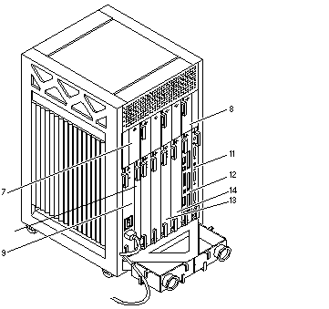 Table F-2 Parts List
|
Key |
Description |
Part Number |
|---|---|---|
|
7 |
Auxiliary fan tray |
540-2757 |
|
8 |
PCM |
300-1260 |
|
9 |
Power supply, peripheral/AC input |
300-1400 |
|
10 |
Interface board |
501-4820 |
|
11 |
Clock+ board assembly |
501-4946 |
|
12 |
SBus+ I/O board assembly |
501-4883 |
|
13 |
Graphics+ I/O board assembly |
501-4884 |
|
14 |
CPU/Memory+ board assembly |
501-4882 |
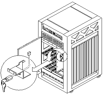
Figure F-3 Key Switch Lock Cable Assembly
|
|
Description |
Part Number |
|---|---|---|
|
|
Key switch lock cable assembly |
530-2148 |
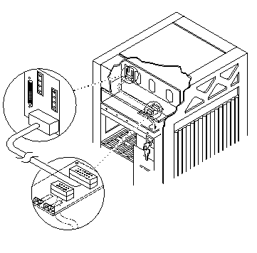
Figure F-4 Key Switch PWB Centerplane Cable Assembly
|
|
Description |
Part Number |
|---|---|---|
|
|
Key switch PWB centerplane cable assembly |
530-2226 |
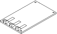
Figure F-5 Key Switch Tray, LED Board
|
|
Description |
Part Number |
|---|---|---|
|
|
LED board |
501-2599 |
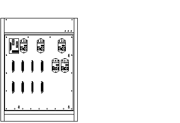
Figure F-6 Centerplane Assembly
|
|
Description |
Part Number |
|---|---|---|
|
|
Centerplane assembly |
501-4799 |
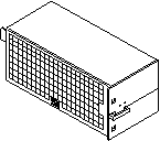
Figure F-7 PCM
|
|
Description |
Part Number |
|---|---|---|
|
|
PCM |
300-1260 |
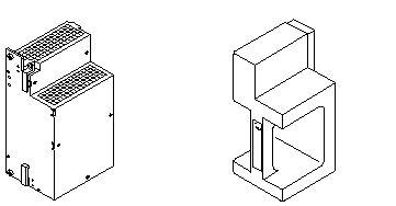
Figure F-8 Peripheral Power Supply (Auxiliary) and Thermal Protection Module
|
|
Description |
Part Number |
|---|---|---|
|
|
Power supply, peripheral |
300-1358 |
|
|
Thermal protection module |
540-3815 |
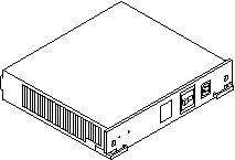
Figure F-9 Peripheral Power Supply/AC Input
|
|
Description |
Part Number |
|---|---|---|
|
|
Power supply, peripheral with AC input |
300-1400 |
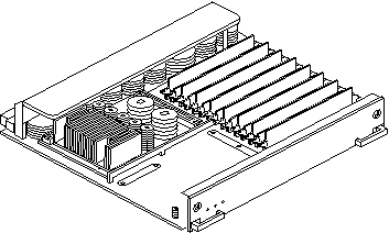
Figure F-10 CPU/Memory+ Board Assembly
|
|
Description |
Part Number |
|---|---|---|
|
|
CPU/Memory+ board assembly (CPU and memory are not included) |
501-4882 |
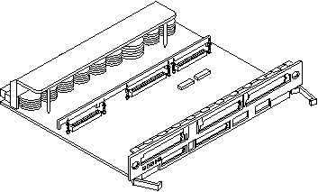
Figure F-11 SBus+ I/O Board Assembly
|
|
Description |
Part Number |
|---|---|---|
|
|
SBus+ I/O board assembly |
501-4883 |
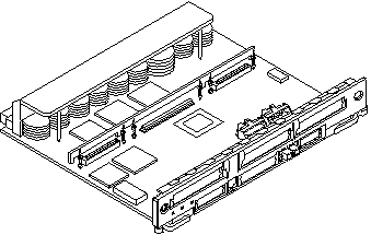
Figure F-12 Graphics+ I/O Board Assembly
|
|
Description |
Part Number |
|---|---|---|
|
|
Graphics+ I/O board assembly |
501-4884 |
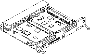
Figure F-13 PCI+ I/O Board Assembly
|
|
Description |
Part Number |
|---|---|---|
|
|
PCI+ I/O board assembly |
501-4926 |
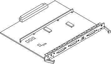
Figure F-14 Clock+ Board Assembly
|
|
Description |
Part Number |
|---|---|---|
|
|
Clock+ board assembly |
501-4946 |
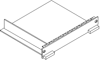
Figure F-15 Filler Board Panel Assembly
|
|
Description |
Part Number |
|---|---|---|
|
|
Filler panel board assembly |
540-2592 |
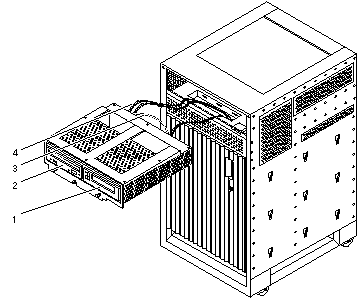
Figure F-16 Media (SCSI) Tray Assembly
|
Key |
Description |
Part Number |
|---|---|---|
|
1 |
Tape drive |
|
|
2 |
Sun CD |
370-3416 |
|
3 |
Media (SCSI) tray data cable assembly |
530-2220 |
|
4 |
SCSI DC power cable assembly |
530-2221 |
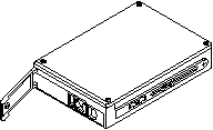
Figure F-17 Disk Drive
|
|
Description |
Part Number |
|---|---|---|
|
|
Disk drive |
540-3249 |
Figure F-18 Fan Tray Assembly
|
|
Description |
Part Number |
|---|---|---|
|
|
Fan tray assembly |
540-3566 |
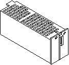
Figure F-19 Auxiliary Fan Tray Assembly
|
|
Description |
Part Number |
|---|---|---|
|
|
Auxiliary fan tray assembly |
540-2757 |
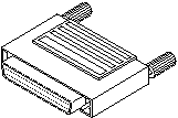
Figure F-20 68-Pin Terminator
|
|
Description |
Part Number |
|---|---|---|
|
|
68-pin terminator |
150-2267 |
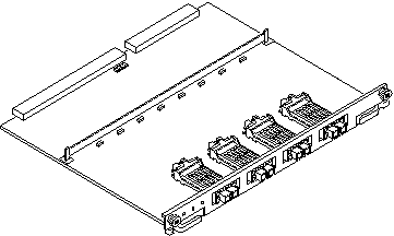
Figure F-21 Interface Board
|
|
Description |
Part Number |
|---|---|---|
|
|
Interface board |
501-4820 |
- © 2010, Oracle Corporation and/or its affiliates
