Appendix G Connectors
CPU/Memory+ Board
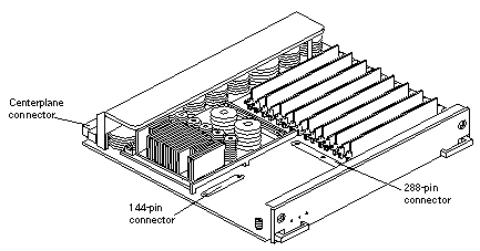
Figure G-1 shows the locations of the centerplane and CPU module connectors.
Figure G-1 CPU/Memory+ Board Connector Locations
Centerplane Connector
Note -
Information for the CPU/Memory+ board centerplane connector also applies to the I/O+ board centerplane connector.
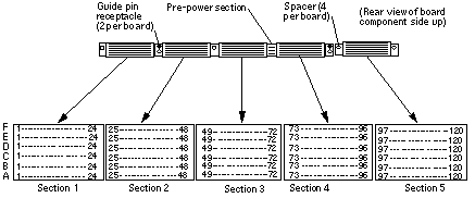
The CPU/Memory+ board centerplane connector is mounted on the rear of the board. The connector is divided into modular sections (see Figure G-2). The connector has one three-bladed power section. The rest of the connector contains six 120-pin rows, labeled A through F. Each section (1 through 5) has 24 pins of each 120-pin row.
Figure G-2 Centerplane Connector Detail
CPU Module Connectors
There are two connectors for each CPU module, one with 144 pins and the other with 288 pins. See Figure G-3.
Figure G-3 CPU Modules 0 and 1

I/O+ Boards
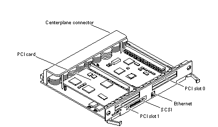
Figure G-4, Figure G-5, and Figure G-6 show the locations of the connectors and slots on the I/O+ boards.
Figure G-4 SBus+ I/O Board Connectors
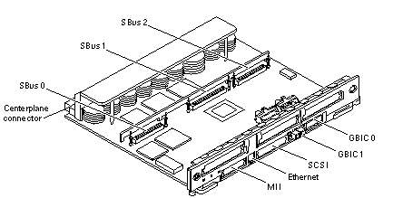
Figure G-5 Graphics+ I/O Board Connectors
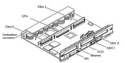
Figure G-6 PCI+ I/O Board Connectors
Centerplane Connector
Information for the CPU/Memory+ board centerplane and the I/O+ boards centerplane is the same. See "Centerplane Connector".
SBus Connectors
Two I/O+ boards have SBus connectors:
-
The SBus+ I/O board has three SBus connectors, SBus 0, 1, and 2. See Figure G-7.
-
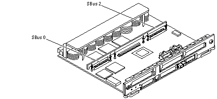
The Graphics+ I/O board has two SBus connectors, SBus 0 and 2. See Figure G-8.
Figure G-7 SBus I/O+ Board SBus Connectors
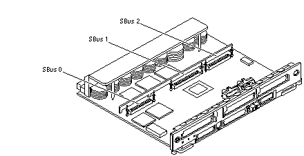
Figure G-8 Graphics+ I/O Board SBus Connectors
UPA Connector Location
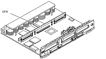
The Graphics+ I/O board has one UPA connector.
Figure G-9 Graphics+ I/O Board UPA Connector
Ethernet and MII Connectors
There is one onboard twisted-pair Ethernet (TPE) connector on the SBus+ I/O board (see Figure G-4), the Graphics+ I/O board (see Figure G-5), and the PCI+ I/O board (see Figure G-6).
There is one media-independent interface connector on the SBus+ I/O board (see Figure G-4) and the Graphics+ I/O board (see Figure G-5). The PCI+ I/O board does not have an MII connector.
Note -
The onboard Ethernet and MII ports share one set of I/O circuitry, so both ports cannot be used at the same time.
GBIC Connectors
Figure G-10 SBus I/O+ Board GBIC Slots
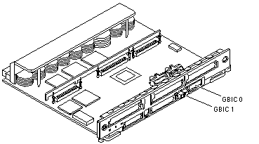
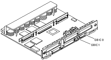
Figure G-11 Graphics+ I/O Board GBIC Slots
PCI Connectors
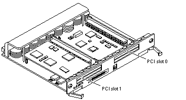
Figure G-12 PCI+ I/O Board Slots
SCSI Connector
There is one on-board SCSI connector on the SBus+ I/O board (see Figure G-4), the Graphics+ I/O board (see Figure G-5), and the PCI+ I/O board (see Figure G-6).
Clock+ Board
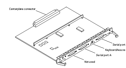
Figure G-13 shows the clock+ board connectors.
Figure G-13 Clock+ Board Connectors
Centerplane Connector
The clock+ board centerplane connector interfaces the board to the system. The connector is divided into six rows of pins labeled A through F; each row has 72 pins.
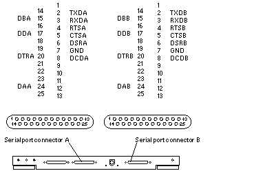
Serial Port Connectors
Figure G-14 Serial Port A and B Connector Pinouts
Keyboard and Mouse Connector
Figure G-15 Keyboard and Mouse Connector Pinouts

Interface Board (IB)
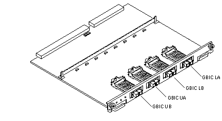
Figure G-16 GBIC Slots
- © 2010, Oracle Corporation and/or its affiliates
