Chapter 3 CPU/Memory+ Boards and Components
To protect both yourself and the equipment, make sure you follow the precautions in Chapter 2, Safety Precautions and Tools Requirements.
For your protection, also observe the following safety precautions when setting up your equipment:
-
Follow all cautions, warnings, and instructions marked on the equipment.
-
Never push objects of any kind through openings in the equipment as they may touch dangerous voltage points or short out components that could result in fire or electric shock.
-
Refer servicing of equipment to qualified personnel.
Handling Boards and Assemblies
The chassis AC power cord must remain connected to ensure a proper ground.
The CPU/Memory+ boards, their modules, and cards have surface-mount components that can be broken by flexing the boards.
To minimize the amount of board flexing, observe the following precautions:
-
Hold the board only by the edges near the middle of the board, where the board stiffener is located. Do not hold the board only at the ends.
-
When removing the board from an antistatic bag, keep the board vertical until you lay it on the Sun ESD mat.
-
Do not place the board on a hard surface. Use a cushioned antistatic mat. The board connectors and components have very thin pins that bend easily.
-
Do not use an oscilloscope probe on the components. The soldered pins are easily damaged or shorted by the probe point.
-
Transport the board in an antistatic bag.
-
Be careful of small parts located on the component side of the board.
The heatsinks on the board can be damaged by incorrect handling. Do not touch the heatsinks while installing or removing the board. Hold the board only by the edges. If a heatsink is loose or broken, obtain a replacement board.
The heatsinks on the board can be damaged by improper packaging. When storing or shipping the board, ensure that the heatsinks have sufficient protection.
Filler Panels
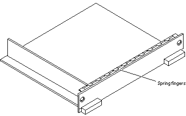
All empty board slots in Enterprise 3500 systems must have a filler panel installed for cooling purposes and for EMI protection. Filler panels are inserted into a board slot with the springfingers facing to the right (Figure 3-1).
-
To remove the filler panel from the card cage, unfasten the captive screws at the top and bottom of the panel.
Grasp the handles to pull the filler panel out.
Figure 3-1 Filler Panel
Hot-Plug Feature
Enterprise 3500 systems have extensive error detection mechanisms, and an Automatic System Reconfiguration (ASR) feature that enables the system to be rebooted with failed components (such as CPUs, memory, or I/O) disabled. When an error is detected, the system can be reconfigured so that the board containing the failed components is placed in low power mode and is no longer accessible.
The peripheral power supply provides the precharge voltages required for hot-plug. Do not attempt hot-plug of a system component if the power supply is inoperative. Use prtdiag(1M)to determine the status of the peripheral power supply.
If the message: NOTICE: Hot Plug not supported in this system is displayed during boot, do NOT attempt hot-plug in this system or damage to the hardware will occur.
The hot-plug feature enables you to insert a new board into a powered-on system, despite being "live," or being supplied with electrical power. Once a working board is added to a powered-on system with the hot-plug feature, the system will not use the new board until the system is rebooted.
CPU/Memory+ Boards
Each CPU/Memory+ board supports up to two UltraSPARC II modules and 16 SIMM slots for memory.
The CPU/Memory+ board includes an Address Controller (AC+), 8 bit-sliced Data Controllers (DC+s), a Bootbus Controller (BC), on-board devices (including a Flash PROM, and SRAM), two CPU processor slots, and slots for two memory banks of 8 SIMMs each.
Removing a Board
Remove a board from a powered-on system only after the ASR software has disabled that board, otherwise, the operating system should be halted and the system powered off prior to board removal. See Chapter 11, Powering Off and On, and then "Removing a Board from a Powered-Off System".
Removing a Board from a Powered-On System
-
Ensure that the board has been disabled by the ASR software. See "Hot-Plug Feature".
Once disabled by ASR, one of two results occurs:
-
The three LEDs on the board are not lit (board has no power).
-
The outer two green LEDs are not lit and the middle yellow LED is lit (board in low power mode).
-
-
Use a Phillips #1 screwdriver to mechanically release the board from the system card cage.
Insert the screwdriver into each quarter-turn access slot (the slots are located on the left and right sides of the board front panel) and then turn a quarter turn so that the arrow points to the unlocked position (Figure 3-2).
Figure 3-2 Unlocking and Locking Quarter-Turn Access Slots

-
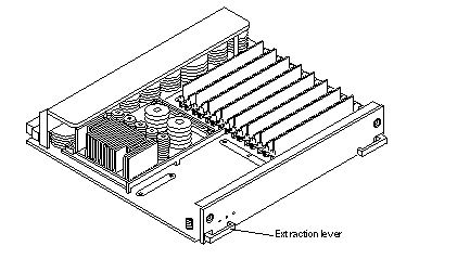
Pull the ends of both extraction levers outward simultaneously to unseat the board centerplane connector from the centerplane receptacles (Figure 3-3).
Figure 3-3 CPU/Memory+ Board
-
If a board is not immediately replaced, a filler panel must be installed in its place.
See "Filler Panels".
Removing a Board from a Powered-Off System
-
Use a Phillips #1 screwdriver to mechanically release the board from the system card cage.
Insert the screwdriver into each quarter-turn access slot (the slots are located on the left and right sides of the board front panel) and then turn a quarter turn so that the arrow points to the unlocked position. See Figure 3-2.
-
Pull the ends of both extraction levers outward simultaneously to unseat the board from the centerplane receptacles (Figure 3-3).
-
If a board is not immediately replaced, a filler panel must be installed in its place.
See "Filler Panels".
Installing a Board
Board Slot Selection
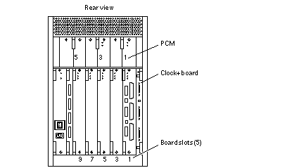
Logically there is no difference between the board slots, and each slot can accept any board type. However, since the lowest numbered board slot (slot 1) is the only slot connected to the onboard SCSI devices, this slot is usually reserved for the first I/O+ board (Figure 3-5).
Note -
Board slot numbers are marked on the chassis.
Figure 3-4 Board Slot Locations
Cooling and Power Issues
There should be one power/cooling module (PCM) for every two boards to adhere to cooling and power requirements. The PCMs must be installed adjacent to populated board slots to ensure the fan in the PCM can cool the respective boards.
Note -
All empty slots must have a filler panel installed to ensure proper cooling and for EMI protection. See "Filler Panels".
Powered-On or Powered-Off System
-
Carefully insert the board in the proper slot in the card cage, component side to the right, ensuring that the board does not slip out of the top and bottom card guides.
All empty slots must have a filler panel installed.
-
Ensure that both extraction levers are in the outward position as you slide the board toward the centerplane receptacles.
The board will not seat fully unless the levers are in this starting position. See Figure 3-3 for positioning of the levers.
 Caution -
 DO NOT FORCE any board into a slot; it can cause damage to the board and system. The board should insert and seat smoothly. If it binds, remove the board and inspect the card cage slot for any obvious obstructions. Also inspect both the board and the centerplane for bent pins or other damage.
-
Push the board into the card cage, then simultaneously press both extraction levers to seat the board on the centerplane.
Pushing both levers simultaneously avoids twisting the board and bending the connector pins, and mates the board centerplane connector to the matching receptacle on the centerplane. Do not press on board front panel to seat it--doing so will damage the connector pins.
-
Mechanically lock the board to the system chassis by inserting a Phillips #1 screwdriver into each quarter-turn access slot and then turning to the locked position.
See Figure 3-2.
-
Once the board is installed, when the system is powered on, a message similar to the following will be displayed on the monitor:
Example depicts screen output when a new CPU/Memory+ board has been hot-plugged into slot 5 of an operating Enterprise system:
NOTICE: CPU Board Hotplugged into Slot 5
NOTICE: Board 5 is ready to remove
Additionally, any subsequent prtdiag(1M) output would include information for board slot 5. Again, note that the system will not use the new board until the system is rebooted.
-
Reboot the system now or schedule a later time to reboot when system disruption will be minimized.
UltraSPARC II Modules
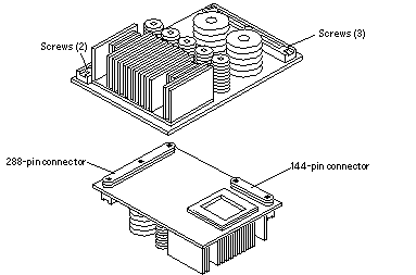
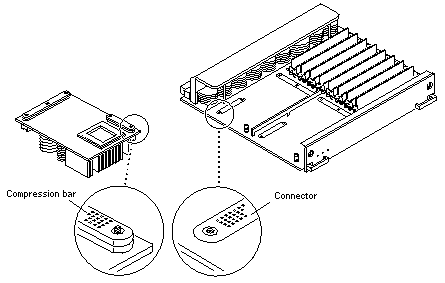
Each CPU/Memory+ board has four connectors for UltraSPARC II modules (up to two modules per board, two connectors per module). For each module, there is a connector with 144 pins and a connector with 288 pins (Figure 3-5).
Figure 3-5 UltraSPARC II Module Connector Detail
Handling Precautions
The following precautions should be exercised when handling UltraSPARC II modules:
-
UltraSPARC II modules are static-sensitive and a grounding wrist strap field kit must be used when handling the modules.
-
Always handle the modules by the edges and not by the smaller black heat sinks that break easily if handled improperly.
-
Do not handle the modules by touching the gold pins on the compression connectors. Natural oils on the hands cause these connectors to oxidize and corrode over a period of time, resulting in the need for module cleaning or replacement.
Removing a Module
Each module is locked to the main board with a single standoff and is connected to the main board by two connectors. The pins within the connectors are compressed to the corresponding board pin receptacles by a metal compression bar which, when secured with screws, compresses the module connector pins to the board receptacle pins (Figure 3-6).
Figure 3-6 UltraSPARC II Module Connector Detail
-
Use the procedures in "Removing a Board" to remove the applicable CPU/Memory+ board.
 Caution -
 The heatsinks on the UltraSPARC II modules may be hot. Use caution when removing or installing UltraSPARC II modules and avoid contact.
-
Use a 3/32 hex driver to loosen all screws from each of the compression bars. Two screws for the 144-pin connector, three screws for the 288-pin connector (Figure 3-5).
-
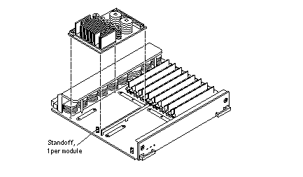
Lift the module straight up off the board mating surface and the single standoff that locks the module to the board (Figure 3-7).
Figure 3-7 UltraSPARC II Module Removal and Replacement
-
Place the module in an antistatic bag.
Installing a Module
To maximize performance when installing UltraSPARC II modules on a CPU/Memory+ board, use all CPU 0 connectors on the lowest numbered slot to the highest numbered slot. After this, if there are modules remaining, use the CPU 1 connectors in the same order.
Note -
Screws on the UltraSPARC II modules must be tightened to 6 inch-pounds. The torque screwdriver that came with your system is set to this specification.
-
Take the UltraSPARC II module out of the protective packaging and inspect for dust on the connectors.
If necessary, clean the connectors with a dry, stiff toothbrush.
-
Remove the applicable CPU/Memory+ board as indicated in "Removing a Board".
-
Inspect the board module mating surface and connectors. If they require cleaning, use a dry, stiff toothbrush to remove debris.
Note -There are miniature silver alignment pins on the compression connectors which, when the module is properly seated, align with related receptacles on the mating surfaces of the CPU/Memory+ board. In addition, there is a gold standoff mounted on the CPU/Memory+ board opposite the module's smaller board connector. This acts as a standoff for the module as well as an alignment pin.
-
Holding the module by the edges, align the module over the two board receptacles (use the single standoff and the alignment pins on the module compression connector as a guide). See Figure 3-6 and Figure 3-7.
-
Rest the module on the board standoff, aligning the compression connectors with the screws.
Firmly but gently press the module straight down until the standoff post snaps into place and the module connectors are fully seated.
-
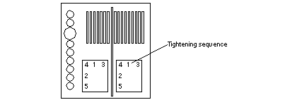
Using the torque screwdriver provided with your system, partially tighten the five 3/32 hex screws:
-
Partially tighten the screws just until they touch the compression connectors in order, beginning with screw 1.
-
Tighten the five screws an additional one-half turn in the same tightening sequence.
-
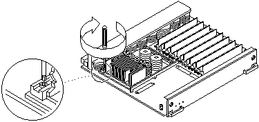
Finish the module installation by tightening all the screws to 6 inch-pounds in the same tightening sequence. See Figure 3-8.
 Caution -
 Do not over torque or under torque the screws. Excessive force can warp the connector. Insufficient force can cause an incomplete electrical connection.
Figure 3-8 Tightening Compression Bar Screws
-
-
Use the procedures in "Installing a Board" to replace the applicable CPU/Memory+ board.
Memory Modules (SIMMs)
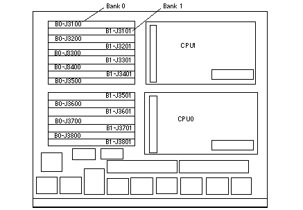
The CPU/Memory+ board has 16 SIMM sockets, which are divided into two banks of 8 SIMMs each, bank 0 and bank 1. Bank 0 and bank 1 SIMMs occupy alternate slot locations; bank 0 SIMMs are in the even numbered slots, and bank 1 SIMMs are in odd numbered slots (Figure 3-9).
Three types of SIMMs can be used in both bank 0 and bank 1.
Table 3-1 SIMM/DRAM|
SIMM |
DRAM |
|---|---|
|
8 Mbyte |
1 Mbyte x 4 |
|
32 Mbyte |
4 Mbyte x 4 |
|
128 Mbyte |
16 Mbyte x 4 |
Figure 3-9 Layout of CPU/Memory+ Board
Removing a Memory Module
-
Remove the CPU/Memory+ board from which the SIMM is to be removed. See "Removing a Board".
-
Attach a wrist strap and place an antistatic surface next to the system.
-
Locate the slot for the SIMM you need to replace. See Figure 3-9.
-
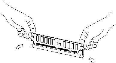
Eject the faulty SIMM by pressing down on the ejection levers on both sides of the SIMM connector. See Figure 3-10.
Figure 3-10 Ejecting a SIMM
-
Holding the SIMM by its edges, remove it from the slot and place it on an antistatic surface.
Installing a Memory Module
Requirements
All banks must have the same size SIMMs. However, SIMMs from different manufacturers are interchangeable in a single bank if the SIMMs all have the same capacity and speed. Sort the SIMMs into banks of eight using the same size SIMMs.
Maximizing Performance
The following guidelines will result in optimal memory interleaving across boards for performance. These guidelines are for optimal performance and are not requirements for a functional system. The guidelines apply to systems with no SIMMS installed and when adding SIMMs to a system. If you are adding SIMMs, you may need to move some SIMMs to meet the guidelines.
-
Install one bank on each board before installing the second bank on any board.
It does not matter whether the first bank is bank 0 or bank 1.
-
Begin with the largest density banks first (128 Mbyte SIMMs), continue with medium sized banks (32 Mbyte SIMMs), and finish with the smallest banks (8 Mbyte SIMMs).
-
If there is remaining memory, start filling the second banks on the boards in the same order as the first banks.
Installation
-
Place the CPU/Memory+ board on which the SIMM is to be installed on an antistatic mat.
-
Carefully remove the new SIMM from its protective packaging and place it on an antistatic surface.
The bag that the SIMM is packed in makes a good antistatic surface.
-
Press down on the ejector levers at both ends of the SIMM connector slot that will receive the new SIMM. See Figure 3-11.
The connector slot will not accept the SIMM unless the levers are in the insert position.
-
Align the SIMM with the slot.
Hold the SIMM by its edges and orient it so that the two notches at the bottom of the SIMM line up with the two tabs in the SIMM connector. See Figure 3-11.
-
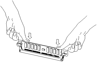
Place your thumbs on the top edge of the SIMM and push the SIMM firmly into its connector.
-
Lock the SIMM in place by pushing both ejector levers into the upright position.
-
Install the CPU/Memory+ board and detach the wrist strap.
See "Installing a Board".
-
As you reboot the system, watch for the system banner to verify that the new memory is recognized by the system.
Figure 3-11 Orienting a SIMM
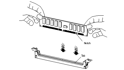
Figure 3-12 Installing a SIMM
- © 2010, Oracle Corporation and/or its affiliates
