Chapter 5 Clock+ Board
To protect both yourself and the equipment, make sure you follow precautions in Chapter 2, Safety Precautions and Tools Requirements.
For your protection, also observe the following safety precautions when setting up your equipment:
-
Follow all cautions, warnings, and instructions marked on the equipment.
-
Never push objects of any kind through openings in the equipment as they may touch dangerous voltage points or short out components that could result in fire or electric shock.
-
Refer servicing of equipment to qualified personnel.
Handling Boards and Assemblies
The chassis AC power cord must remain connected to ensure a proper ground.
The clock+ board and its modules have surface-mount components that can be broken by flexing the board.
To minimize the amount of board flexing, observe the following precautions:
-
Hold the board only by the edges near the middle of the board, where the board stiffener is located. Do not hold the board only at the ends.
-
When removing the board from an antistatic bag, keep the board vertical until you lay it on the Sun ESD mat.
-
Do not place the board on a hard surface. Use a cushioned antistatic mat. The board connectors and components have very thin pins that bend easily.
-
Do not use an oscilloscope probe on the components. The soldered pins are easily damaged or shorted by the probe point.
-
Transport the board in an antistatic bag.
Clock+ Board
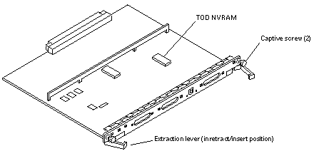
There is one clock+ board for each Enterprise 3500 system (see Figure 5-1). The clock+ board provides:
-
Programmable system and processor clock
-
Serial, keyboard, and mouse ports for the console
-
Centralized Time-of-day (TOD) chip that includes NVRAM
-
Centralized reset logic
-
Status and control of power supplies
The clock+ board consists of the following subsystems:
-
ConsoleBus
-
Clocks
-
Reset logic
-
JTAG
-
Centerplane connector signals
Figure 5-1 Clock+ Board

ConsoleBus
The ConsoleBus provides system boards access to global system control and status as well as to the keyboard, mouse, and serial ports. In addition, there is a NVRAM/TOD chip that maintains the date and time and 8 Kbytes of data when the power to the system is shut off.
The state of physical hardware conditions is maintained in registers on the clock+ board. Each of these registers has inputs generated from other subsystems on the clock+ board, from other boards, or from the power supplies in the system. Some clock+ board registers are reserved for controlling various states of the machine.
The ConsoleBus also provides a serial port interface and a keyboard/mouse interface. The primary purpose of the serial port interface is to provide POST messages during power on. The serial port can be used as a console for systems without a keyboard and display, and for standard serial peripheral hook-ups such as modems and printers.
Clocks
The clock subsystem generates the clocks for the entire system. The base clock is synthesized and then divided into various frequencies. The base clocks are then "fanned-out" and driven to the centerplane by an array of driver chips. Two processor clocks and one system clock go to each of the board slots on the centerplane.
Reset logic
The reset logic consists of four subcircuits for controlling the system reset and error state:
-
Manual reset
-
System reset
-
XIR
-
System error
Removing a Clock+ Board
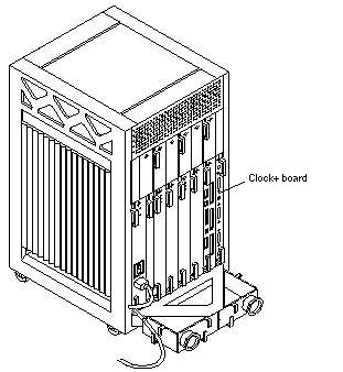
The clock+ board slot is located in the system rear, to the right of the board slots. See Figure 5-2.
The clock+ board is not hot pluggable. Do not remove the clock+ board until the system has been halted and powered off.
You must halt the operating system before turning off the system power. See Chapter 11, Powering Off and On for this procedure.
To avoid damaging internal circuits, do not disconnect or connect any cable while power is applied to the system.
-
Halt the operating system and turn off the system power. See Chapter 11, Powering Off and On for this procedure.
-
Unfasten cable connectors from the board front panel and set them aside.
Label cables to identify them for reconnection later.
-
Loosen the two captive screws securing the board to the system card cage.
-
Pull the ends of both extraction levers outward simultaneously to unseat the board from the centerplane receptacles.
See Figure 5-1 to position the extraction levers.
Installing a Clock+ Board
The clock+ board slot is located in the system rear, to the right of the board slots. See Figure 5-2.
Figure 5-2 Clock+ Board Location

Note -
If you are replacing the clock+ board, the TOD NVRAM from the old board must be removed and placed on the new board. Note also that if a system is replaced, then the TOD NVRAM on the clock+ board must also be changed.
-
Carefully insert the board in the proper slot in the card cage, ensuring that the board does not slip out of the top and bottom card guides.
The component side of the board must face to the right.
-
Ensure that both extraction levers are in the outward position as you slide the board toward the centerplane connectors.
See Figure 5-1 to position the extraction levers. The board will not seat fully unless the levers are in this starting position.
 Caution -
 DO NOT FORCE any board into a slot; this can cause damage to the board and system. The board should insert and seat smoothly. If it binds, remove the board and inspect the card cage slot for any obvious obstructions. Also inspect both the board and the centerplane for bent pins or other damage.
-
Use the extraction levers to seat the board.
Simultaneously swing both levers into the locked position. Do not press on board to seat it; doing so will damage the connector pins.
-
Secure the board to the chassis using the two captive screws, one on each side.
See Figure 5-1.
-
Connect any applicable interface cables to the system board back panel.
-
Turn on system power. See Chapter 11, Powering Off and On for this procedure.
-
Boot the system.
- © 2010, Oracle Corporation and/or its affiliates
