Chapter 6 Interface Board
To protect both yourself and the equipment, make sure you follow precautions in Chapter 2, Safety Precautions and Tools Requirements.
For your protection, also observe the following safety precautions when setting up your equipment:
-
Follow all cautions, warnings, and instructions marked on the equipment.
-
Never push objects of any kind through openings in the equipment as they may touch dangerous voltage points or short out components that could result in fire or electric shock.
-
Refer servicing of equipment to qualified personnel.
Handling Boards and Assemblies
The chassis AC power cord must remain connected to ensure a proper ground.
The interface board and its modules have surface-mount components that can be broken by flexing the board.
To minimize the amount of board flexing, observe the following precautions:
-
Hold the board only by the edges near the middle of the board, where the board stiffener is located. Do not hold the board only at the ends.
-
When removing the board from an antistatic bag, keep the board vertical until you lay it on the Sun ESD mat.
-
Do not place the board on a hard surface. Use a cushioned antistatic mat. The board connectors and components have very thin pins that bend easily.
-
Do not use an oscilloscope probe on the components. The soldered pins are easily damaged or shorted by the probe point.
-
Transport the board in an antistatic bag.
Filler Panels
All empty board slots in Enterprise 3500 systems must have a filler panel installed for cooling purposes and for EMI protection. Filler panels are inserted into a board slot with the springfingers facing to the right.
-
To remove the interface board filler panel from the card cage, unfasten the captive screws at the top and bottom of the panel.
Grasp the handles to pull the filler panel out.
Interface Board
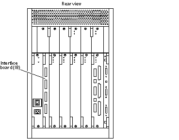
Each Enterprise 3500 system has a slot for one interface board (IB). The IB, which is optional, is installed in the rear of the system, adjacent to the peripheral power supply/AC. See Figure 6-1.
Note -
Enterprise 3500 systems must have either an IB or a filler panel installed in the IB slot.
Figure 6-1 Interface Board Location

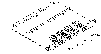
The interface board provides mounting for four GBICs (see Figure 6-2) together with associated circuitry. A GBIC (Gigabit Interface Converter) is a hot-pluggable unit that converts any of the standard Fibre Channel connectors and signaling technologies. Within this manual, the GBIC Fibre Channel is 100 Mbytes.
Essentially, the interface board receives, reclocks, and provides bypass services for four independent FC-AL ports. The interface board, together with interconnecting fiber optic cabling, provides four independent FC-AL loops between the host I/O+ board and the internal fiber optic disks.
Figure 6-2 Interface Board
 Table 6-1 GBIC Controllers for Disk Drive Ports
|
Disk Drives |
Drive Port |
GBIC Name and Location |
|---|---|---|
|
0, 1, 2, 3 |
A |
GBIC LA (Lower bank) |
|
0, 1, 2, 3 |
B |
GBIC LB (Lower bank) |
|
4, 5, 6, 7 |
A |
GBIC UA (Upper bank) |
|
4, 5, 6, 7 |
B |
GBIC UB (Upper bank) |
Removing an Interface Board
Note -
It is not necessary to remove the interface board from the card cage to remove and replace GBICs. A GBIC may be removed and replaced "live" (without removing power from the system or board). However, the necessary software precautions must be taken whenever the I/O path to a particular disk is to be interrupted; halt all I/O activity to the disk affected by the replacement of a GBIC. To replace a GBIC or fiber optic cable, proceed to "Removing a GBIC".
-
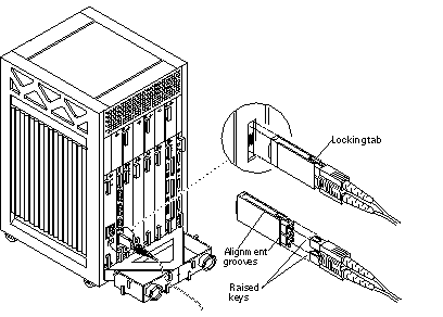
Unfasten any fiber optic cables from the board front panel and set them aside. See Figure 6-3.
Label cables to identify them for reconnecting.
Figure 6-3 Removal of Fiber Cable and GBIC

-
Loosen the two captive screws securing the board to the system card cage.
-
Pull the ends of both extraction levers outward simultaneously to unseat the board from the centerplane receptacles.
Installing an Interface Board
-
Carefully insert the board in the proper slot in the card cage, ensuring that the board does not slip out of the top and bottom card guides.
The component side of the board must face to the right.
-
Ensure that both extraction levers are in the outward position as you slide the board toward the centerplane connectors.
The board will not seat fully unless the levers are in this starting position.
 Caution -
 DO NOT FORCE any board into a slot; this can cause damage to the board and system. The board should insert and seat smoothly. If it binds, remove the board and inspect the card cage slot for any obvious obstructions. Also inspect both the board and the centerplane for bent pins or other damage.
-
Use the extraction levers to seat the board.
Simultaneously swing both levers into the locked position. Do not press on board to seat it; doing so will damage the connector pins.
-
Secure the board to the chassis using the two captive screws.
-
Reonnect any fiber optic cables to the board front panel.
Removing a GBIC
Note -
It is not necessary to remove the interface board from the card cage to remove and replace GBICs. A GBIC may be removed and replaced "live" (without removing power from the system or board). However, the necessary software precautions must be taken whenever the I/O path to a particular disk is to be interrupted; halt all I/O activity to the disk affected by the replacement of a GBIC.
To remove a GBIC, first remove the fiber optic cable as shown in Figure 6-3. Then compress the two locking tabs while pulling the GBIC straight out as depicted in Figure 6-3.
Installing a GBIC
Note -
It is not necessary to remove the interface board from the card cage to remove and replace GBICs. A GBIC may be removed and replaced "live" (without removing power from the system or board). However, the necessary software precautions must be taken whenever the I/O path to a particular disk is to be interrupted; halt all I/O activity to the disk affected by the replacement of a GBIC.
Ensure that the orientation of the alignment groove is correct (Figure 6-3) and then reinsert the GBIC into the proper slot. Reconnect the fiber optic cable as depicted in Figure 6-3 (keys on cable matching notches on the GBIC).
- © 2010, Oracle Corporation and/or its affiliates
