Chapter 7 Power Supplies
This chapter describes the power supplies and environmental sensing and reporting in Enterprise 3500 systems.
There are three types of power supplies:
-
Peripheral power supply/AC input (PPS/AC [PPS 0])
-
Optional auxiliary peripheral power supply (PPS [PPS 1])
-
Power/cooling module (PCM)
A thermal protection module or an auxiliary peripheral power supply (PPS1) must be installed in the front PPS1 slot at all times to ensure the maximum operating temperature is not exceeded.
Both the auxiliary peripheral power supply (PPS 1) and the PCM are hot-pluggable. This feature enables you to physically remove the failed component despite its being "live," or being supplied with electrical power. In addition, both may be inserted into a running system.
The PPS/AC (PPS 0) is not hot-pluggable because it incorporates an AC cord and circuit breaker for system input power.
Note -
A functioning PPS/AC (PPS 0) provides electrical precharge that is required for the hot plug of PCMs. The hot-plug replacement of the PPS (PPS 1) does not require electrical precharge. Use the prtdiag (1M) command to determine if electrical precharge is available.
Table 7-1 lists the power supply voltages, their uses, and the power supplies that generate them.
Table 7-1 Power Supply Summary|
Voltage |
Supply |
Use |
|---|---|---|
|
2.0V |
PCM |
Centerplane termination |
|
3.3V |
PCM |
CPU/Memory+ Board, I/O+ Board, Clock+ Board UltraSPARC II Module (SRAMs, SDBs, CPU I/O) |
|
5V |
PCM |
SBus Card, Clock+ Board UltraSPARC II Module power (via DC/DC converter) |
|
5V |
PPS/AC, PPS |
Peripherals (CD drive, tape drive) |
|
12V |
PPS/AC, PPS |
Peripherals (CD drive, tape drive) |
Safety Precautions
To protect both yourself and the equipment, any servicing of equipment should be performed by qualified personnel. Observe the precautions in Table 7-2.
Table 7-2 Safety Precautions|
Item |
Problem |
Precaution |
|---|---|---|
|
Wrist or foot strap |
ESD |
Wear a conductive wrist strap or foot strap when handling power supplies. |
|
ESD mat |
ESD |
An approved ESD mat provides protection from static damage when used with a wrist strap or foot strap. |
|
Cover panels |
System damage and overheating |
Re-install all cabinet cover panels after performing any service work on the system. |
|
SBus slot covers |
System damage and overheating |
Install SBus slot covers in all unused SBus slots. |
Distribution
In the Enterprise 3500 system, there is at least one peripheral power supply and a PCM slot for each pair of board slots. There is a single alternating current (AC) power cord for the whole system. AC is then distributed to each of the PCMs within the chassis. The software monitors the status of the AC power source. Current sharing between power supplies provides redundant power.
Peripheral Power Supplies
The PPS/AC (PPS 0) Figure 7-1 and the auxiliary PPS (PPS 1) shown in Figure 7-2 provide power to the peripheral subsystems, the remote console, and the drives.
Note -
Either a thermal protection module (see Figure 7-2) or an auxiliary peripheral power supply must be installed in the PPS1 slot whenever a system is powered-on.
Both the PPS/AC (PPS 0) and auxiliary PPS (PPS 1) incorporate current sharing to operate in redundant and parallel operations. The peripheral power supply/AC input provides three precharge outputs (3.3V, 5V, and 12V) to enable hot-plug installation of system boards or PCMs into an active centerplane.
Figure 7-1 Peripheral Power Supply/AC Input
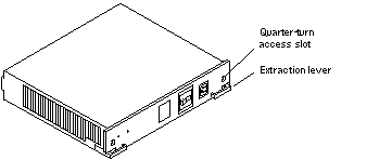
Figure 7-2 Auxiliary Peripheral Power Supply (PPS1) and Thermal Protection Module
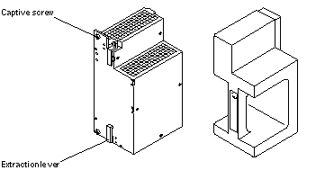
Peripheral Power Supply LEDs
A green LED is lit on the power supply when it is operational. When a peripheral power supply fails, a yellow LED is lit on the power supply.
See Table 10-6 for more information.
Replacing the Peripheral Power Supply/AC (PPS 0)
-
Completely power off the Enterprise 3500 system.
See the power off instructions in Chapter 11, Powering Off and On.
-
Disconnect the AC power cord from the power inlet.
-
Release the power supply from the system chassis by inserting a Phillips #1 screwdriver into each quarter-turn access slot and then turning to the unlocked position. See Figure 7-3.
Figure 7-3 Unlocking and Locking Quarter-turn Access Slots

-
Pull the ends of the extraction levers outward to release the power supply from the centerplane.
-
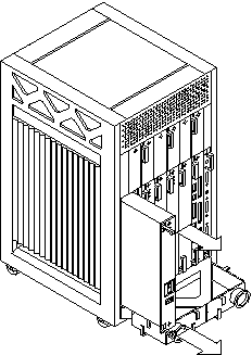
Pull out the power supply. See Figure 7-4.
Figure 7-4 Replacing the Peripheral Power Supply/AC Input
-
Carefully insert the replacement power supply in the proper slot using the guide slots.
Ensure that both extraction levers are in the outward position. The power supply will not seat fully unless the levers are in this starting position.
-
Slide the power supply toward the centerplane.
Ensure that the arrows in the quarter-turn access slots point to the unlocked position. See Figure 7-3.
 Caution -
 DO NOT FORCE the power supply into a slot; this can cause damage to the power supply and system.
The power supply should insert and seat smoothly. If it binds, remove it, and inspect the slot for any obvious obstructions. Do not damage the springfingers at the bottom of the power supply.
-
Use the extraction levers to seat the power supply.
Simultaneously swing both levers inward to the locked position. Do not press on the front panel of the power supply to seat it--doing so will damage the connector pins.
-
Lock the power supply to the system chassis by inserting a Phillips #1 screwdriver into each quarter-turn access slot and then turning to the locked position. See Figure 7-3.
-
Connect the AC cord and power on the Enterprise 3500 system.
See the power on instructions in Chapter 11, Powering Off and On.
-
Check to be sure the green LED on the power supply is lit.
If the green LED is not lit, the power supply may not be seated properly. Check to see if it is seated properly by repeating Step 6 to Step 11. If the green LED is still not lit, see Table 10-6 for more information.
Replacing the Thermal Protection Module or Auxiliary Peripheral Power Supply (PPS1)
All Enterprise 3500 systems must have either a thermal protection module or an auxiliary peripheral power supply (PPS1) installed in the PPS1 slot in the front of the system.
Removing a Thermal Protection Module
-
Use the key provided to unlock and open the system front door.
-
Grasp the handle on the thermal protection module and firmly pull the module toward you, out of the PPS1 slot in the system chassis.
-
Before powering on the system, install an auxiliary peripheral power supply or return the thermal protection module to the PPS1 slot.
Replacing an Auxiliary Peripheral Power Supply
Remove and replace the auxiliary peripheral power supply (PPS 1) in a running system but not in the low power mode. In low power mode, the front panel and board LEDs are all off, while the yellow LEDs are lit on the power supplies. Replacing the PPS (PPS 1) during low power mode causes the system to power on immediately.
-
Use the key provided to unlock and open the system front door.
-
Release the power supply from the system chassis by loosening the captive screws.
-
Pull the ends of the extraction levers outward to release the power supply from the centerplane.
-
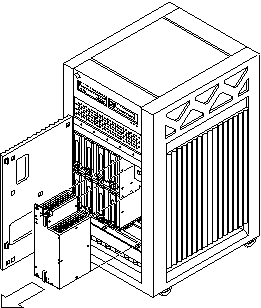
Pull the power supply straight out.
You will see a message similar to the following example on your system console:
NOTICE: Peripheral Power Supply 1 Removed
Figure 7-5 Replacing the Auxiliary Peripheral Power Supply (PPS1)
-
Carefully insert the replacement power supply in the PPS1 slot.
Ensure that both extraction levers are in the outward position. The power supply will not seat fully unless the levers are in this starting position.
-
Slide the power supply toward the centerplane.
 Caution -
 DO NOT FORCE the power supply into a slot; this can cause damage to the power supply and system.
The power supply should insert and seat smoothly. If it binds, remove it, and inspect the slot for any obvious obstructions.
-
Use the extraction levers to seat the power supply.
Simultaneously swing both levers inward to the locked position. Do not press on the front panel of the power supply to seat it--doing so will damage the connector pins.
-
Lock the power supply to the system chassis by tightening the captive screws.
-
Check to be sure the green LED on the power supply is lit.
If the green LED is not lit, the power supply may not be seated properly. Check to see if it is seated properly by repeating Step 5 to Step 9. If the green LED is still not lit, see Table 10-6 for more information.
If the green LED is lit, you will see a message similar to the following example on your system console:
NOTICE: Peripheral Power Supply 1 Installed

NOTICE: Peripheral Power Supply 1 OK
Power/Cooling Module (PCM)
The power/cooling module (PCM, see Figure 7-6) provides power for two boards. The PCM also supplies cooling air to the board slots, so in normal operation each board must be next to a working PCM.
Figure 7-6 PCM

The PCM incorporates an AC inrush limit circuit and two precharge inputs (3.3V and 5V) that enable it to be hot-pluggable into a live centerplane.
Within a system all PCMs operate in a parallel redundant mode, sharing 2.0V, 3.3V, and 5V output currents. The shared 5V output also includes the 5V output of a peripheral power supply.
Requirements for Redundant Power
If a DC supply in a PCM fails, the system boards will continue to be powered and cooled by the other power supplies if sufficient redundancy (an additional power supply) is present.
For example, if an Enterprise 3500 system needs a minimum of two PCMs and three are present, then the system has redundancy. See Table 7-3.
Note -
The presence of an additional (extra) PCM in the system provides redundancy and allows hot-plug of PCMs.
Table 7-3 Minimum and Redundant Working Power Supplies Required to Power Active Boards
|
|
Enterprise 3500 System |
|
|---|---|---|
|
Number of Boards |
Minimum Number of Working PCMs |
Redundant Working PCMs (Hot-Pluggable) |
|
1-2 |
1 |
2 |
|
3-4 |
2 |
3 |
|
5 |
3 |
No redundancy |
Note -
When all five board slots are populated, there is no redundancy because of the two PCMs per board rule.
Failed power supplies must be replaced as soon as practical. Otherwise, the Enterprise 3500 system will lose its redundancy and result in an outage at the next PCM failure.
Cooling Requirements
Note -
In the Enterprise 3500 system, all boards must be adjacent to a PCM. The fans in the PCM cool the boards. The minimum configuration is one PCM for every two adjacent boards.
The PCMs incorporate redundant bulk fan power so that the fans continue to operate in a failed power supply via the redundant fan power from the peripheral power supply.
Note -
A PCM or an auxiliary fan tray must be working in PCM slot 5. The fans cool the peripheral power supply/AC input.
Troubleshooting a PCM
A green LED is lit on the power supply when it is operational. When a PCM fails, a yellow LED is lit on the PCM.
You will see a message similar to the following example on your system console when a PCM fails:
WARNING: Core Power Supply 3 Failing
WARNING: Redundant power lost
See Table 10-6 for more information.
Replacing a PCM
Do not replace a PCM while the system is in the low power mode. Remove and replace the PCM only in a running system. Replacing a PCM during low power mode will cause the system to power up immediately and result in a severe overload condition for that PCM (the other PCMs will remain in the low power mode). The system is in the low power mode if the front panel and board LEDs are all off while the yellow LEDs are lit on the power supplies.
Replace the PCM immediately or risk overheating the board(s) cooled by the fans in that power supply.
Remember the following rules for hot-plug replacement of a PCM:
-
The peripheral power supply/AC (PPS0) must be fully operational (to provide precharge current).
-
There must be a redundancy of electrical power (see Table 7-3) in the system.
-
Use the prtdiag (1M) command to determine if precharge current is present.
-
Release the power supply from the system chassis by inserting a Phillips #1 screwdriver into each quarter-turn access slot and then turning to the unlocked position. See Figure 7-7.
Figure 7-7 Quarter-turn Access Slots

-
Pull the end of the extraction lever outward to release the power supply from the centerplane.
-
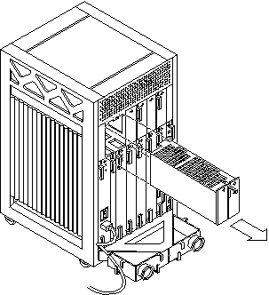
Pull out the power supply. See Figure 7-8.
You will see a message similar to the following example on your system console:
NOTICE: Core Power Supply 5 Removed
Figure 7-8 Replacing a PCM in the Enterprise 3500 System
-
Carefully insert the replacement power supply in the proper slot.
-
Orient the PCM with the extraction lever on the outside edge of the Enterprise 3500 system.
-
Verify that the arrows in the quarter-turn access slots are turned to the unlocked position.
-
Ensure that the extraction lever is in the outward, unlocked position.
The power supply will not seat fully unless the lever is in the unlocked position.
 Caution -
 DO NOT FORCE the power supply into a slot. This can cause damage to the power supply and system.
The power supply should insert and seat smoothly. If it binds, remove it, and inspect the slot for any obvious obstructions. Do not damage the springfingers at the bottom of the power supply.
-
-
Slide the power supply toward the centerplane, then use the extraction lever to seat the power supply. See Figure 7-8.
Swing the lever inward to the locked position. Do not press on the front panel of the power supply to seat it--doing so will damage the connector pins.
-
Lock the power supply to the system chassis by inserting a Phillips #1 screwdriver into each quarter-turn access slot and then turning to the locked position. See Figure 7-7.
-
Check to be sure the green LED on the PCM is lit.
If the green LED is not lit, the power supply is not seated properly. Repeat Step 5 to Step 8. If the green LED is still not lit, see Table 10-6 for more information.
If the green LED is lit, you will see a message similar to the following example on your system console:
NOTICE: Core Power Supply 5 Installed
NOTICE: Core Power Supply 5 OK
NOTICE: Redundant power available
- © 2010, Oracle Corporation and/or its affiliates
