Auxiliary Fan Tray Assembly
Removing the Auxiliary Fan Tray Assembly
-
Locate the auxiliary fan tray assembly at the back of the system.
Viewed from the rear of the system, the auxiliary fan tray is on the upper left side of the chassis, in PCM slot 5 (slot 5 can contain either an auxiliary fan tray or a PCM).
-
Release the auxiliary fan tray from the system chassis by inserting a Phillips #1 screwdriver into each quarter-turn access slot and turning to the unlocked position. See Figure E-2.
Figure E-2 Unlocking and Locking Quarter-Turn Access Slots

-
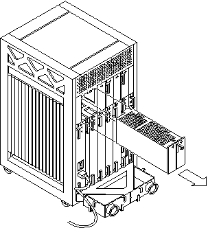
Pull the end of the extraction lever outward to release the auxiliary fan tray assembly from the centerplane. See Figure E-3.
Figure E-3 Removing the Auxiliary Fan Tray

-
Slowly remove the auxiliary fan tray assembly from the chassis and set it aside.
Replacing the Auxiliary Fan Tray Assembly
-
Carefully insert the auxiliary fan tray into the slot at the back of the Enterprise 3500 system.
-
Ensure that the extraction lever is in the outward position.
-
Orient the auxiliary fan tray with the extraction lever on the outside edge of the Enterprise 3500 system. See Figure E-3.
-
-
Slide the auxiliary fan tray assembly toward the centerplane.
The auxiliary fan tray assembly will not seat fully unless the lever is in this starting position.
 Caution -
 DO NOT FORCE the auxiliary fan tray assembly into the slot; this can cause damage to the auxiliary fan tray and system.
The auxiliary fan tray assembly should insert and seat smoothly. If it binds, remove it, and inspect the slot for any obvious obstructions. Do not damage the springfingers at the bottom of the auxiliary fan tray assembly.
-
Swing the extraction lever inward to the locked position to seat the auxiliary fan tray assembly.
Do not press on the front panel of the auxiliary fan tray assembly to seat it; doing so will damage the connector pins.
-
Lock the auxiliary fan tray to the system chassis by inserting a Phillips #1 screwdriver into each quarter-turn access slot and then turning to the locked position. See Figure E-2).
- © 2010, Oracle Corporation and/or its affiliates
