Appendix B Functional Description
System Overview
The Enterprise 6500, 5500, and 4500 servers all use variations of the same general card cage design. All systems feature shared-memory multiprocessors and use the same boards, power/cooling modules (PCMs), and operating software.
Board Types
All systems use the same board types, with the exception of load boards and filler panels.
-
The CPU/Memory+ board supports up to two UltraSPARC II modules and 16 SIMM slots.
-
The SBus+ I/O board includes two SYSIO ASICs that provide two SBuses: one for two plug-in SBus cards and two GBIC (100 MB/sec Fibre Channel) interfaces, and one for one plug-in SBus card and the onboard devices (10/100 Mbit TPE and Single-ended Fast/Wide SCSI).
-
The Graphics+ I/O board includes one SYSIO ASIC that provides a single SBus for two plug-in SBus cards, two GBIC (100 MB/sec Fibre Channel) interfaces, and the onboard devices (10/100 Mbit TPE and Single-ended Fast/Wide SCSI).
-
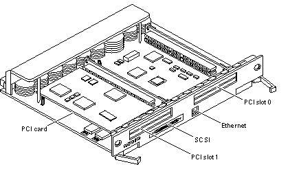
The PCI+ I/O board has two PCI bus connectors, each of which can accommodate a PCI riser card. Each riser card accommodates one PCI short card. In addition, onboard devices provide Fast Ethernet (10/100 Mbit) and Fast/Wide SCSI interfacing.
-
In the Enterprise 6500 system, empty board slots require load boards (part number 501-3142) to reduce the possibility of RFI generation. The Enterprise 5500 and 4500 systems use filler panels (part number 540-2592).
Basic Definitions for the Card Cage
When locating a board slot in the 8-slot and 16-slot card cages, remember:
Table B-1 Card Cage Definitions|
Slot numbers |
Even-numbered slots are at the front of the card cage. Odd-numbered slots are at the back. |
|
|
In the front of the card cage, slot 0 is at the top. At the rear of the card cage, slot 1 is at the top. |
|
|
The component side of a board is down in the front slots. The component side is up in the rear slots. |
|
|
For specific slot numbers, see Appendix B, "Enterprise 4500 Standalone Server". |
|
Slot functions |
All card cage slots are equivalent in the Enterprise 6500, 5500, and 4500 systems. However, it is suggested that you install I/O+ boards at the back of the cage to simplify the installation of interface cables. Install CPU/Memory+ boards at the front of the cage to leave the rear slots for I/O+ boards. If all slots are filled on one side of the cage, you can use the other side. |
|
|
Slot 1 should contain an I/O+ board connected to the boot disk. (This is a suggestion, and not a requirement.) |
|
|
Slot 0 should contain a CPU/master board with at least one CPU. The POST diagnostics display more messages if slot 0 contains a CPU/Memory+ board and a CPU. For an explanation, see the next item, "Master board." |
|
Master board |
The first CPU/Memory+ board (in slot 0) functions temporarily as a master board during some POST tests. There is no master board during normal system operations after the POST tests have finished. |
Enterprise card cages feature a centerplane bus. Boards at the front of the centerplane must be installed component side down, while boards at the back must be installed component side up. The boards are oriented this way to allow for minimum signal trace lengths and optimum system performance.
Figure B-1 illustrates the logical organization of Enterprise systems.
Figure B-1 Enterprise System Logical Organization
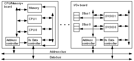
There are few differences between board slots and each slot can accept any board type. However, an I/O+ board should be installed in slot 1 since this slot connects directly to the internal media tray through the centerplane and related cables. The internal tape and/or CD-ROM or other optional internal SCSI drives cannot be used unless an I/O+ board is present in slot 1.
Although the remaining slots are equivalent, I/O+ boards should be located on the back side of the centerplane for easy access to interface cables at the rear of the cabinet.
System Packaging
This section describes the features of the system enclosures.
Enterprise 6500 Server
The Enterprise 6500 server features a 16-slot card cage in a 68-inch data center system cabinet (Figure B-2).
Figure B-2 Sun Enterprise System Cabinet
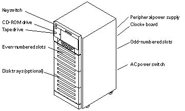
The front of the cabinet contains the CD-ROM/tape tray, the keyswitch, the even-numbered board slots, and the even-numbered power/cooling module (PCM) slots.
The rear of the cabinet contains the AC power switch, the peripheral power supply, the clock+ board, the odd-numbered board slots, and the odd-numbered PCM slots.
For slot numbers in the 16-slot card cage, see Figure 3-5.
Air circulation for the system boards is provided by the power/cooling modules. The PCMs (PCM 0 through PCM 7) have two fans each. The fans provide cooling for the PCM, plus two adjacent board slots. There is also a fan tray in the card cage (item 11 in Figure F-2). A second fan tray is located at the side of the rack (Figure F-7), The rear of the media tray also has a fan.
All empty board slots must be blocked by load boards for proper airflow, cooling, and EMI protection. Other types of empty slots must be blocked by filler panels.
Enterprise 5500 Server
The Enterprise 5500 server is similar to the Enterprise 6500 system but features a shorter, 8-slot, card cage. See Figure B-2.
For slot numbers in the 8-slot card cage, see Figure B-3.
Figure B-3 Enterprise 5500 Server
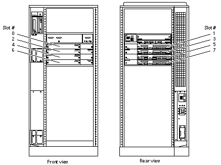
Functionally, the 16-slot and 8-slot cabinet servers are the same, with the only difference being the board capacity and amount of internal space available below the card cage. All boards are interchangeable between the two versions.
All empty slots must be blocked by filler panels for proper airflow, cooling, and EMI protection.
Note -
The load board that is required for the 16-slot Enterprise 6500 server is not required for the Enterprise 5500.
Enterprise 4500 Standalone Server
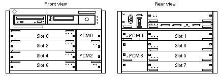
The Enterprise 4500 server uses the 8-slot card cage that is used for the Enterprise 5500, but the card cage is in a standalone cabinet (Figure B-4).
Also note that several areas of the card cage that are covered by filler panels in the cabinet version are used in the standalone version. These areas include the SCSI CD-ROM/tape tray, keyswitch, and AC switch (Figure B-4).
The power/cooling modules (PCM 0 through PCM 3) each have two fans. The fans provide cooling for the PCM and the two adjacent board slots. Air circulation for the system boards is provided by the power/cooling modules. In addition, the Enterprise 4500 has a combined AC input box and fan tray.
All empty slots must be blocked by filler panels for proper airflow, cooling, and EMI protection.
Figure B-4 Enterprise 4500 Standalone Server
Software
The Enterprise software includes two diagnostic packages, Solstice SyMON and SunVTS. Refer to the online manuals for operating instructions.
Board Hot-Plug Procedures
The CPU/Memory+ board and the I/O+ board are hot-pluggable under certain conditions. If the operating system detects a hardware failure in the board, the system powers down the corresponding board slot and turns off the left green status LED on the board. (See Table 9-2 for LED codes.)
When the left green LED is off, it is safe to remove the board even though the system continues running.
CPU/Memory+ Board
The CPU/Memory+ board (Figure B-5) supports up to 2 CPU modules and 16 SIMMs.
Figure B-5 CPU/Memory+ Board
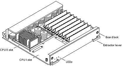
The CPU/Memory+ board should be installed from the smallest even-numbered slot (0) to the largest even-numbered slot (14). The even-numbered slots are located at the front of the cabinet. When located in these slots, the component side of the board is down. If the front slots are filled, you can use slots at the rear of the cabinet, with the exception of slot 1. Slot 1 requires an I/O+ board because the slot connects to the media tray in the front of the cabinet.
All empty slots must have a filler panel or load board installed.
Note -
The 16-slot Enterprise 6500 card cage requires load boards to reduce the potential for RFI generation. The 8-slot Enterprise 5500 and 4500 card cages use filler panels, which do not have load circuits.
CPU Modules
Each CPU/Memory+ board has two sets of CPU connectors, marked PROC 0 and PROC 1.
The order in which you fill CPU slots is not critical. However, to optimize heat dissipation in the system:
-
Fill all PROC 0 locations on all CPU/Memory+ boards before filling any PROC 1 locations. To receive the maximum quantity of diagnostic information, fill PROC 0 on board 0.
-
After all PROC 0 locations are filled, you may begin filling the PROC 1 locations, again starting from the lowest slot number to the highest.
System Master Board
The board slots are interchangeable. A system master board is selected for the duration of POST and OBP testing, to control the testing processes. The system master is normally the lowest-numbered slot containing a board with a functional CPU. After the tests are finished, the board slots are again fully equivalent.
SIMMs
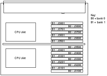
The CPU/Memory+ board has 16 slots for SIMMs, organized as two banks of eight SIMMs.
Slot Locations
SIMMs must be installed in full banks of eight. Figure B-6 shows the slot numbers for bank 0 and bank 1.
Figure B-6 SIMM Slot Locations
SIMM Selection
The JEDEC standard 3.3 volt SIMMs are available in 8, 32, or 128 Mbyte capacities. All are 168-pin SIMMs.
Do not mix different capacities in a bank.
The Enterprise systems SIMMs operate at 3.3V -- do not substitute other voltage ratings.
I/O+ Boards
Several types of I/O+ boards are available: SBus+ I/O board, Graphics+ I/O board, and PCI+ I/O board.
For easy access to I/O cables, I/O+ boards should be installed in the rear of the cabinet, with CPU/Memory+ boards in the front of the cabinet. I/O+ boards should be installed from the smallest odd-numbered slot (1) to the largest odd-numbered slot (7 or 15). The odd-numbered slots are located at the rear of the cabinet. When located in these slots, the board is oriented so that the component side is up.
Note -
Board slot 1 requires an SBus+ or Graphics+ I/O board because this is the only slot that connects with the internal media tray. If slot 1 does not contain an I/O+ board, the drives in the media tray will not function.
If the rear slots are filled, you can use slots at the front of the cabinet. When located in a front slot, the board is oriented so that the component side is down.
Note -
All empty card cage slots must contain a load board (Enterprise 6500 server) or filler panel (Enterprise 5500 or 4500 servers).
SBus+ I/O Board
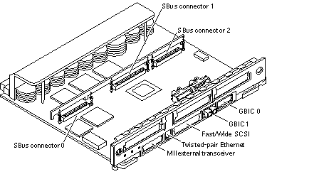
The SBus+ I/O board with 100 MB/sec Fibre Channel (Figure B-7) includes two SYSIO ASICs that provide two SBuses:
-
One for two plug-in SBus cards and two GBIC (100 MB/sec Fibre Channel) interfaces
-
One for one plug-in SBus card and the onboard devices (10/100 Mbit TPE and Single-ended Fast/Wide SCSI)
Note -
SBus connector slots 1 and 2 on the SBus+ I/O board can accommodate a double-wide SBus card.
Figure B-7 SBus+ I/O Board
Graphics+ I/O Board
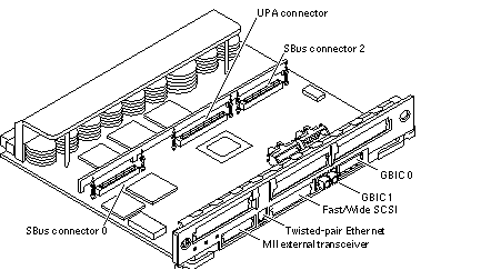
The Graphics+ I/O board with 100 MB/sec Fibre Channel (Figure B-8) includes one SYSIO ASIC that provides a single SBus for two plug-in SBus cards, two GBIC (100 MB/sec Fibre Channel) interfaces, and the onboard devices (10/100 Mbit TPE and Single-ended Fast/Wide SCSI).
Figure B-8 Graphics+ I/O Board
PCI+ I/O Board
The PCI+ I/O board (Figure B-9) has two PCI bus connectors:
-
Each connector can accommodate a PCI riser card
-
Each riser card accommodates one PCI short card
In addition, onboard devices on the PCI+ I/O board provide Fast Ethernet (10/100 Mbit) and Fast/Wide SCSI interfacing.
Figure B-9 PCI+ I/O Board
The board contains five subsystems: I/O (PCI Bus), Memory, Bus Interface, FireHose Interface, and Clock Generation. Four of these subsystems: the I/O (PCI Bus), Memory, Bus Interface and internal board interface subsystems include ASICs. The Clock subsystem distributes and generate clocks for the ASICs and PCI Bus Interfaces on the board
Network Interfaces
Each SBus+ I/O board and Graphics+ I/O board has onboard connectors for 10BASE-T or 100BASE-T Ethernet. The two sockets (RJ-45 and 40-pin MII) connect to the same interface circuit, so that only one socket is active at any time.
Additional network interfaces can be added in the form of SBus cards. The SBus+ I/O board will support up to three SBus interface cards. The Graphics+ I/O board will support up to two SBus interface cards.
Disk Board
The Disk board (with two SCSI disks) is an available option for the Enterprise systems. The Enterprise 6500 system supports two Disk boards (only in slots 14 and 15); the Enterprise 5500 and 4500 systems support four Disk boards.
The ID settings of the two disks on the Disk board vary according to the card cage slot location. See Appendix C, SCSI Devices.
Power Supplies
There are two types of power supplies: power/cooling modules (PCMs) and peripheral power supplies. PCMs provide DC current and cooling air to boards in the card cage. The peripheral power supply provides current for peripheral devices (such as a tape or CD-ROM drive) in the media tray.
Power/Cooling Modules (PCMs)
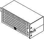
The DC power to the centerplane is supplied by one or more PCMs. Each PCM also provides cooling air for two board slots. If a slot contains a board, the adjacent PCM slot must contain a PCM to supply cooling air.
Current from individual PCMs is shared on the centerplane.
With automatic system reconfiguration (ASR), a PCM can be taken offline and replaced without halting the system. There are two restrictions:
-
The remaining power/cooling modules must provide sufficient electrical power. As a general rule, the number of boards must be less than half the number of PCMs.
-
The PCM should be replaced quickly so that any adjacent boards will not overheat from lack of fan cooling.
Figure B-10 PCM
Peripheral Power Supply
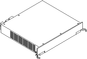
A system has one peripheral power supply. This power supply provides DC power for the CD-ROM/tape tray and precharge power for hot-plugging boards and power/cooling modules. The +5 VDC output of the peripheral power supply is current shared with the +5 VDC outputs of the power/cooling modules.
Figure B-11 Peripheral Power Supply
Clock+ Board
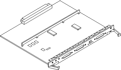
The clock+ board is located at the rear of the system, directly below the peripheral power supply. When replacing the clock+ board, orient the board with the component side up (Figure B-12).
The clock+ board provides 16 pairs of system clocks, 32 pairs of processor clocks.
All processors run at the same clock speed. The system clock and the processor clocks are derived from a single clock source. The frequency of the clock source as well as the processor and system clocks are programmable and set by firmware. The processor clock frequency is set to match the lowest-frequency processor in the system.
The clock+ board also includes central devices including serial ports, keyboard and mouse, and a time-of-day (TOD) chip.
Figure B-12 Clock+ Board
Disk Arrays
Enterprise systems support Fibre Channel-Arbitrated Loop (FC-AL) disk drive arrays.
CD-ROM/Tape Tray
All Enterprise servers include a media tray for one CD-ROM drive and one tape drive. The drives connect to the wide SCSI connector of the first I/O+ board (in card cage slot 1).
-
Enterprise 6500/5500 servers-- the media tray is located in the front upper left part of the rack, and the drives are mounted vertically. (Up to four additional SCSI drives may be mounted in the area to the right of the CD-ROM/tape tray.)
-
Enterprise 4500 server--the media tray is located in the front, immediately above the card cage, and the drives are mounted horizontally. (The Enterprise 4500 server does not have space for additional internal drives.)
- © 2010, Oracle Corporation and/or its affiliates
