Removing a Module
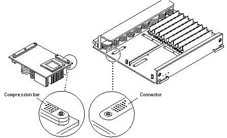
Each module is locked to the main board with a single standoff and is connected to the main board by two connectors. The pins within the connectors are compressed to the corresponding board mating surfaces by a metal compression bar which, when secured with screws, compresses the module connector pins to the board mating surfaces (Figure 3-9).
Figure 3-9 Ultra SPARC Module Connector Detail

-
Use the procedures in "Removing a Board", to remove the applicable CPU/Memory+ board.
 Caution -
 The heatsinks on the UltraSPARC II modules may be hot. Use caution when removing or installing UltraSPARC II modules and avoid contact.
-
Use a 3/32 Hex driver to loosen all screws on each of the compression connectors on the module to be removed (three screws for the 288-pin connector, two screws for the 144-pin connector) (Figure 3-8).
-
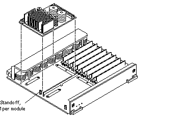
Lift the module straight up, off the board mating surface and the single standoff that locks the module to the board.
Use pressure applied with fingers to assist in removing module from standoff (Figure 3-10).
Figure 3-10 UltraSPARC II Module Removal and Replacement

-
Place the module in an antistatic bag.
- © 2010, Oracle Corporation and/or its affiliates
