SBus Cards
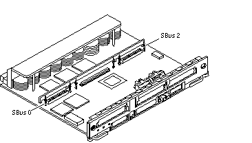
There are three SBus card locations on the SBus+ I/O board; the Graphics+ I/O board has two.
Figure 4-12 SBus+ I/O Board SBus Card Connectors
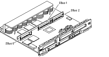
Figure 4-13 Graphics+ I/O Board SBus Card Connectors
Nylon Standoffs
Nylon standoffs lock the SBus and graphics (UPA) cards to the I/O+ boards (Figure 4-14).
-
To unlock a standoff, pull up the tip insert.
-
To lock a standoff, first ensure that the module or card rests on the standoff flange, then press down the tip insert.
Figure 4-14 Locking and Unlocking Standoffs

Removing an SBus Card
-
Use the procedures in "Removing a Board", to remove the applicable I/O+ board.
-
Use Figure 4-12 to locate the card to be removed.
-
Remove the two screws that secure the SBus card to the back panel.
Save the screws for installation of a replacement SBus card or a filler panel.
-
Unlock the SBus card by pulling up the tips of the two standoff (Figure 4-14).
-
Hold the card by the edges near the connector and gently rock the card back and forth to loosen it from the socket.
You may have to remove the SBus cards or the FFB card next to this card in order to have enough room to hold onto the SBus card being removed.
 Caution -
 The connector housing may break if the SBus card is tilted too far.
-
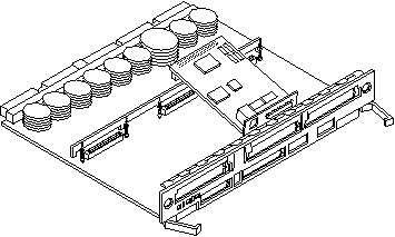
Lift the SBus card from the socket at an angle while guiding the face plate out from the back panel opening (Figure 4-15).
Figure 4-15 Removing or Installing an SBus Card
-
Place the SBus card in an antistatic bag for protection.
-
If the SBus card is not immediately replaced, install a filler panel (part number 340-2305) on the I/O+ board back panel opening. To secure the filler panel, use the screws that were removed in Step 1.
 Caution -
 Be sure to install the filler panel right-side up. Installing it upside down creates a gap at the top edge of the SBus slot opening that can impair system cooling and FCC regulatory compliance.
-
Replace the I/O+ board. Use the procedures in "Installing a Board".
Installing an SBus Card
Removing Adapter and Card Retainer
Note -
If the new SBus card does not have an adapter plate or card retainer, proceed to "Installation".
-
Attach a wrist strap and take the SBus card out of the protective packaging and place the SBus card on an antistatic mat.
-
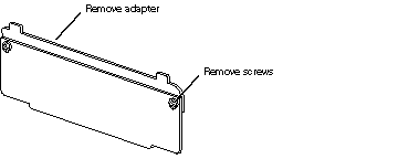
Remove the adapter bracket from the SBus card rear panel (Figure 4-16).
Remove the two screws securing the adapter to the card rear panel (the adapter bracket and the screws are not needed for this installation).
Figure 4-16 SBus Card Rear Panel with Adapter
-
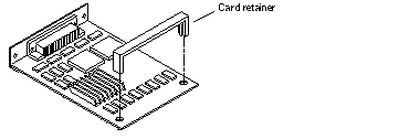
Remove the black plastic card retainer shipped with the card (Figure 4-17).
Spread the ends of the retainer apart to remove it from the card (the retainer is not needed for this installation).
Figure 4-17 Card Retainer
Link Integrity Test
Note -
If the new SBus card does not have a link integrity test proceed to "Installation".
For the system to communicate with a network, the tpe-link-test? settings for the onboard Ethernet ports must be compatible with the setting at the network hub. The tpe-link-test? variable is set separately for the onboard Ethernet port on each I/O+ board. The variable is also set for any SBus Ethernet cards in the system.
If you have problems verifying connection between Sun equipment and your hub, verify that your hub also has the link test function enabled. Also, refer to the manual provided with your hub.
-
Place the SBus card on an antistatic mat.
-
For DSBE/S and FSBE/S cards: remove the two outer retaining screws (Figure 4-18), but do NOT remove the middle screw or the springfinger.
Use a #0 Phillips screwdriver and a 3/16 nut driver or socket wrench.
-
For DSBE/S and FSBE/S cards, configure jumper J0302 for Link Integrity Test functionality. See Figure 4-18 (DSBE/S) or Figure 4-19 (FSBE/S).
-
Put the shunt over both pins to disable the Link Integrity Test (Figure 4-20 "Disabled")
-
Put the shunt in one pin to enable the Link Integrity Test (Figure 4-20 "Enabled").
 Caution -
 If you choose to disable the test, it must be disabled both at the hub and at the SBus card. In the event of "loss of carrier" or "not responding" errors, check the status of the link enable on both the SBus card and the hub.
Figure 4-18 DSBE/S SBus Card
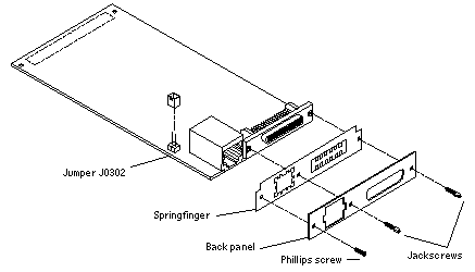
Figure 4-19 FSBE/S SBus Card
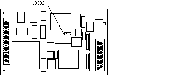
Figure 4-20 Disabling and Enabling the Link Integrity Test

-
Installation
-
Use the procedures in "Removing a Board", to remove the applicable I/O+ board.
-
Use Figure 4-12 to locate the SBus connector for the card that is to be installed.
-
If a filler panel covers the back panel SBus slot, remove the two screws and detach the filler panel.
Retain the screws to attach the SBus card to the back panel, unless the card has a wide connector, or set of connectors.
-
Unlock the tip insert of the two standoffs for the SBus slot (Figure 4-14).
-
Attach a wrist strap and take the SBus card out of the protective packaging. Inspect the pins in the connector to make sure they are not bent.
-
Hold the SBus card at an angle and guide the SBus card face plate under the springfingers and against the rear face of the I/O+ board front panel.
See Figure 4-15. The I/O connectors of the SBus card should be visible through the opening in the back panel.
-
Hold the card by the edges nearest the SBus connector and place the card over the two standoffs.
-
Hold the SBus card by the edges near the connector and firmly but gently press the card down until the connector is fully seated.
To align the connector and socket, push the card toward the I/O+ board back panel.
 Caution -
 Do not rock the card onto the socket; the plastic connector housing may break.
-
Press each corner of the SBus card to ensure that it rests on the collar of the standoff.
-
Press down on the tip insert of each standoff to lock the card in place.
-
Replace and tighten the back panel screws to secure the SBus card to the I/O+ board back panel.
-
Replace the I/O+ board using the procedures described in "Installing a Board".
- © 2010, Oracle Corporation and/or its affiliates
