I/O+ Boards
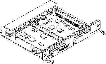
Enterprise 6500/5500/4500 systems support three types of I/O+ boards: SBus+ I/O board with 100 MB/sec Fibre Channel, Graphics+ I/O board with 100 MB/sec Fibre Channel, and PCI+ I/O board. Each board has three LEDs that provide board status codes (Figure 4-4 through Figure 4-6).
GBIC
Each SBus+ and Graphics+ I/O board provides mounting for two GBIC interfaces. A GBIC (Gigabit Interface Converter) is a hot-pluggable unit that converts any of the standard Fibre Channel connectors and signaling technologies. The GBIC Fibre Channel referred to in this manual is 100 Mbytes/second.
Figure 4-4 SBus+ I/O Board with 100 MB/sec Fibre Channel
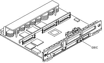
Figure 4-5 Graphics+ I/O Board with 100 MB/sec Fibre Channel
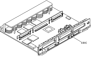
Figure 4-6 PCI+ I/O Board
The SBus+ I/O board with 100 MB/sec Fibre Channel includes two SYSIO ASICs that provide two SBuses:
-
One for two plug-in SBus cards and two GBIC interfaces
-
One for one plug-in SBus card and the onboard devices (10/100 Mbit TPE and Single-ended Fast/Wide SCSI).
Note -
SBus connector slots 1 and 2 on the SBus+ I/O board can accommodate a double-wide SBus card.
The Graphics+ I/O board with 100 MB/sec Fibre Channel includes one SYSIO ASIC that provides a single SBus for two plug-in SBus cards, two GBIC interfaces, and the onboard devices (10/100 Mbit TPE and Single-ended Fast/Wide SCSI).
The PCI+ I/O board has two PCI bus connectors:
-
Each connector can accommodate a PCI riser card
-
Each riser card accommodates one PCI short card
In addition, onboard devices on the PCI+ I/O board provide Fast Ethernet (10/100 Mbit) and Fast Wide SCSI interfacing.
Removing a Board
Note -
It is not necessary to remove an I/O+ board from the card cage to remove and replace GBICs. A GBIC may be removed and replaced "live" (without removing power from the system or board). However, the necessary software precautions must be taken whenever the I/O path to a particular disk is to be interrupted; halt all I/O activity to the disk affected by the replacement of a GBIC. To replace a GBIC or fiber optic cable, proceed to "GBICs".
Removing a Board from a Powered-On System
Remove a board from a powered-on system only after the ASR software has disabled the board. If a board has not been disabled by the ASR software, then the operating system should be halted and the system powered off prior to board removal. See Chapter 11, Powering Off and On , then "Removing a Board from a Powered-Off System".
-
Ensure that the board has been disabled by the ASR software. See "Hot-Plug Feature".
Once disabled by ASR, one of two results occurs:
-
The three LEDs on the board are not lit (board has no power).
-
The outer two green LEDs are not lit and the middle yellow LED is lit (board is in low power mode).
Note -System software operates such that the LED pattern described is the same for a board that is component side down (installed in front of card cage) or component side up (installed in rear of card cage).
-
-
Unfasten any cable connectors from the front panel and set them aside.
Label cables to identify them for reconnection later.
-
Use a Phillips #1 screwdriver to mechanically release the board from the system card cage.
Insert the screwdriver into each quarter-turn access slot (the slots are located on the left and right sides of the board front panel) and then turn a quarter turn so that the arrow points to the unlocked position (Figure 4-7).
Figure 4-7 Unlocking and Locking Quarter-Turn Access Slots

-
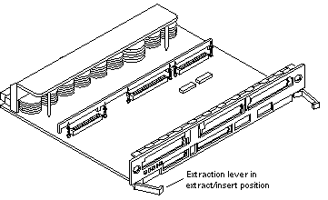
Pull the ends of both extraction levers outward simultaneously to unseat the board centerplane connector from the centerplane receptacles (Figure 4-8).
Figure 4-8 Extraction Lever in Extract Position
-
If a board is not immediately replaced, a load board (Enterprise 6500 systems only) or a filler panel (Enterprise 4500 and 5500 systems only) must be installed in its place.
Removing a Board from a Powered-Off System
-
Use a Phillips #1 screwdriver to mechanically release the board from the system card cage.
Insert the screwdriver into each quarter-turn access slot (the slots are located on the left and right sides of the board front panel) and then turn a quarter turn so that the arrow points to the unlocked position (Figure 4-7).
-
Unfasten any cable connectors from the front panel and set them aside.
Label cables to identify them for reconnection later.
-
Pull the ends of both extraction levers outward simultaneously to unseat the board from the centerplane receptacles (Figure 4-8).
-
If a board is not immediately replaced, a load board (Enterprise 6500 systems only) or a filler panel (Enterprise 4500 and 5500 systems only) must be installed in its place before powering on the system.
Installing a Board
Board Slot Selection
Note -
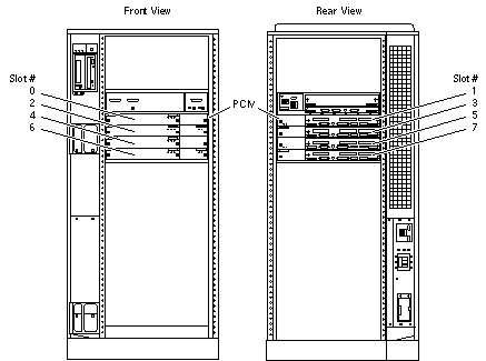
Logically there is no difference between the board slots in the front or rear of the card cage, and each slot can accept any board type. It is suggested that CPU/Memory+ boards be installed in the front slots, and I/O+ and Disk boards be installed in the rear slots because of cabling. Should the need arise, however, any of these three board types can be placed in any of the numbered board slots, with the exception of slot 1. Slot 1 should be used by the first I/O+ board because it is the only slot connected to the onboard SCSI devices.
The first CPU/Memory+ board is placed in slot 0, followed sequentially by all remaining even numbered slots. If there are boards remaining, they can be installed sequentially in odd numbered slots, if available, in the system rear (with the exception of slot 1 as noted above) (Figure 4-9 and Figure 4-10).
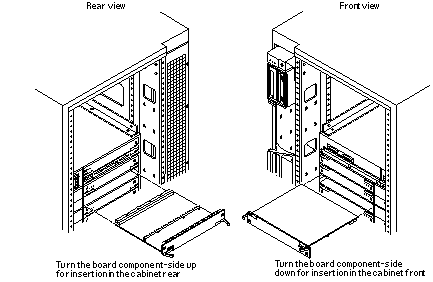
For I/O+ boards being placed in the rear of the system, ensure that the component side is up. If the boards are placed in the front of the system, ensure that the component side is down (Figure 4-11).
Figure 4-9 Enterprise 6500 Board Locations
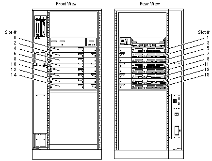
Figure 4-10 Enterprise 5500/4500 Board Locations
Cooling and Power Issues
There should be one power/cooling module (PCM) for every two boards to adhere to cooling and power requirements. The PCMs must be installed adjacent to populated board slots to ensure the fan in the PCM can cool the respective boards.
Note -
All empty board slots in Enterprise 6500 systems must have a load board installed to ensure proper cooling and for EMI protection. All empty board slots in Enterprise 5500 or 4500 systems must have a filler panel installed.
Inserting a System Board
-
Carefully insert the board (component side down if in front; component side up if in the rear) in the proper slot in the card cage, ensuring that the board does not slip out of the left and right card guides (Figure 4-11).
Figure 4-11 Board Replacement
-
Ensure that both extraction levers are in the insert position (arrow pointing outward), and that the quarter-turn access slots are unlocked (arrow indicates unlocked position) as you slide the board toward the centerplane receptacles.
The board will not seat fully unless the levers are in this starting position and the access slots are unlocked. See Figure 4-7, and Figure 4-8.
 Caution -
 DO NOT FORCE any board into a slot; this can cause damage to the board and system. The board should insert and seat smoothly. If it binds, remove the board and inspect the card cage slot for any obvious obstructions. Also inspect both the board and the centerplane for bent pins or other damage.
-
Push the board into the card cage, then simultaneously press both extraction levers to seat the board on the centerplane.
Pushing both levers simultaneously avoids twisting the board and bending the connector pins, and mates the board centerplane connector to the matching receptacle on the centerplane. Do not press on board front panel to seat it--doing so will damage the connector pins.
-
Mechanically lock the board to the system chassis by inserting a Phillips #1 screwdriver into each quarter-turn access slot and then turning to the locked position (Figure 4-7).
-
Replace or connect all necessary cables to the front of the board.
Note -The I/O+ board in slot 1 controls the internal media tray devices. Therefore, the external SCSI connector on the I/O+ board in slot 1 of a system must be terminated with a SCSI terminator (Figure 4-3).
-
Terminate the board SCSI connector if required, see above note.
-
Once the board has been installed, a message similar to the following will be displayed on the monitor (if the system is powered on):
The example depicts screen output when a new I/O+ board has been hot-plugged into slot 6 of an operating Enterprise system:
NOTICE: I/O Board Hotplugged into Slot 6
NOTICE: Board 6 is ready to remove
This screen output indicates that the board has been detected by the system and is in the low power mode. Additionally, any subsequent prtdiag(1M) output would include information for board slot 6. Again, note that the system will not use the new board until the system is rebooted.
-
Reboot the system now or schedule a later time to reboot when system disruption will be minimized.
SBus Cards
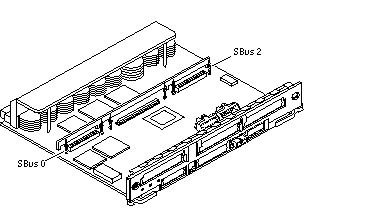
There are three SBus card locations on the SBus+ I/O board; the Graphics+ I/O board has two.
Figure 4-12 SBus+ I/O Board SBus Card Connectors
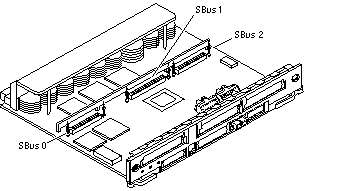
Figure 4-13 Graphics+ I/O Board SBus Card Connectors
Nylon Standoffs
Nylon standoffs lock the SBus and graphics (UPA) cards to the I/O+ boards (Figure 4-14).
-
To unlock a standoff, pull up the tip insert.
-
To lock a standoff, first ensure that the module or card rests on the standoff flange, then press down the tip insert.
Figure 4-14 Locking and Unlocking Standoffs

Removing an SBus Card
-
Use the procedures in "Removing a Board", to remove the applicable I/O+ board.
-
Use Figure 4-12 to locate the card to be removed.
-
Remove the two screws that secure the SBus card to the back panel.
Save the screws for installation of a replacement SBus card or a filler panel.
-
Unlock the SBus card by pulling up the tips of the two standoff (Figure 4-14).
-
Hold the card by the edges near the connector and gently rock the card back and forth to loosen it from the socket.
You may have to remove the SBus cards or the FFB card next to this card in order to have enough room to hold onto the SBus card being removed.
 Caution -
 The connector housing may break if the SBus card is tilted too far.
-
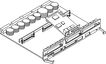
Lift the SBus card from the socket at an angle while guiding the face plate out from the back panel opening (Figure 4-15).
Figure 4-15 Removing or Installing an SBus Card
-
Place the SBus card in an antistatic bag for protection.
-
If the SBus card is not immediately replaced, install a filler panel (part number 340-2305) on the I/O+ board back panel opening. To secure the filler panel, use the screws that were removed in Step 1.
 Caution -
 Be sure to install the filler panel right-side up. Installing it upside down creates a gap at the top edge of the SBus slot opening that can impair system cooling and FCC regulatory compliance.
-
Replace the I/O+ board. Use the procedures in "Installing a Board".
Installing an SBus Card
Removing Adapter and Card Retainer
Note -
If the new SBus card does not have an adapter plate or card retainer, proceed to "Installation".
-
Attach a wrist strap and take the SBus card out of the protective packaging and place the SBus card on an antistatic mat.
-
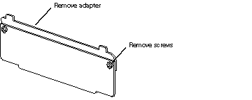
Remove the adapter bracket from the SBus card rear panel (Figure 4-16).
Remove the two screws securing the adapter to the card rear panel (the adapter bracket and the screws are not needed for this installation).
Figure 4-16 SBus Card Rear Panel with Adapter
-
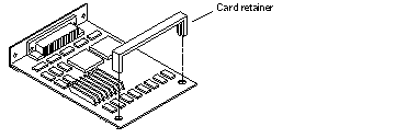
Remove the black plastic card retainer shipped with the card (Figure 4-17).
Spread the ends of the retainer apart to remove it from the card (the retainer is not needed for this installation).
Figure 4-17 Card Retainer
Link Integrity Test
Note -
If the new SBus card does not have a link integrity test proceed to "Installation".
For the system to communicate with a network, the tpe-link-test? settings for the onboard Ethernet ports must be compatible with the setting at the network hub. The tpe-link-test? variable is set separately for the onboard Ethernet port on each I/O+ board. The variable is also set for any SBus Ethernet cards in the system.
If you have problems verifying connection between Sun equipment and your hub, verify that your hub also has the link test function enabled. Also, refer to the manual provided with your hub.
-
Place the SBus card on an antistatic mat.
-
For DSBE/S and FSBE/S cards: remove the two outer retaining screws (Figure 4-18), but do NOT remove the middle screw or the springfinger.
Use a #0 Phillips screwdriver and a 3/16 nut driver or socket wrench.
-
For DSBE/S and FSBE/S cards, configure jumper J0302 for Link Integrity Test functionality. See Figure 4-18 (DSBE/S) or Figure 4-19 (FSBE/S).
-
Put the shunt over both pins to disable the Link Integrity Test (Figure 4-20 "Disabled")
-
Put the shunt in one pin to enable the Link Integrity Test (Figure 4-20 "Enabled").
 Caution -
 If you choose to disable the test, it must be disabled both at the hub and at the SBus card. In the event of "loss of carrier" or "not responding" errors, check the status of the link enable on both the SBus card and the hub.
Figure 4-18 DSBE/S SBus Card
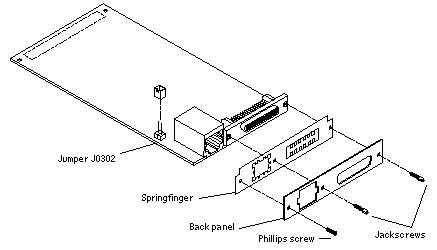
Figure 4-19 FSBE/S SBus Card
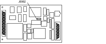
Figure 4-20 Disabling and Enabling the Link Integrity Test

-
Installation
-
Use the procedures in "Removing a Board", to remove the applicable I/O+ board.
-
Use Figure 4-12 to locate the SBus connector for the card that is to be installed.
-
If a filler panel covers the back panel SBus slot, remove the two screws and detach the filler panel.
Retain the screws to attach the SBus card to the back panel, unless the card has a wide connector, or set of connectors.
-
Unlock the tip insert of the two standoffs for the SBus slot (Figure 4-14).
-
Attach a wrist strap and take the SBus card out of the protective packaging. Inspect the pins in the connector to make sure they are not bent.
-
Hold the SBus card at an angle and guide the SBus card face plate under the springfingers and against the rear face of the I/O+ board front panel.
See Figure 4-15. The I/O connectors of the SBus card should be visible through the opening in the back panel.
-
Hold the card by the edges nearest the SBus connector and place the card over the two standoffs.
-
Hold the SBus card by the edges near the connector and firmly but gently press the card down until the connector is fully seated.
To align the connector and socket, push the card toward the I/O+ board back panel.
 Caution -
 Do not rock the card onto the socket; the plastic connector housing may break.
-
Press each corner of the SBus card to ensure that it rests on the collar of the standoff.
-
Press down on the tip insert of each standoff to lock the card in place.
-
Replace and tighten the back panel screws to secure the SBus card to the I/O+ board back panel.
-
Replace the I/O+ board using the procedures described in "Installing a Board".
Graphics (UPA) Cards
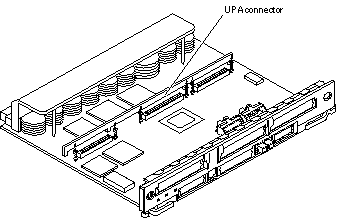
The Graphics+ I/O board contains a single connector that accommodates graphics (UPA) cards (Figure 4-21).
Figure 4-21 Graphics (UPA) Card Connector Location
Removing a Graphics (UPA) Card
-
Use the procedures in "Removing a Board", to remove the applicable Graphics+ I/O board.
-
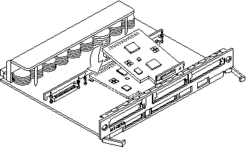
Locate the card (Figure 4-22).
-
Remove the two screws that secure the card to the Graphics+ I/O board front panel.
Save the screws for installation of a replacement card or a filler panel.
-
Unlock the card by pulling up the tips of the two standoffs (Figure 4-14).
-
Hold the card by the edges near the connector and gently rock the card back and forth to loosen it from the socket.
You may have to remove the SBus cards next to this card in order to have enough room to hold onto the graphics (UPA) card being removed.
 Caution -
 The connector housing may break if the card is tilted too far.
-
Lift the card from the socket at an angle while guiding the face plate out from the back panel opening (Figure 4-22).
Figure 4-22 Removing or Installing a Graphics (UPA) Card
-
Place the card in an antistatic bag.
-
If the graphics (UPA) card is not immediately replaced, install a filler panel (part number 340-2305) on the Graphics+ I/O board back panel opening. To secure the filler panel, use the screws that were removed in Step 1.
 Caution -
 Be sure to install the filler panel right-side up. Installing it upside down creates a gap at the top edge of the card slot opening that can impair system cooling and regulatory compliance.
-
Use the procedures in "Installing a Board", to replace the Graphics+ I/O board.
Installing a Graphics (UPA) Card
-
Use the procedures described in "Removing a Board", to remove the applicable Graphics+ I/O board.
Note -The connector pins on graphics (UPA) cards are extremely delicate, use care when handling.
-
Attach a wrist strap and take the graphics (UPA) card out of the protective packaging and place the card on an antistatic mat.
Inspect the pins in the connector to make sure they are not bent.
-
Remove the adapter bracket from the rear panel of the card (Figure 4-16).
Remove the two screws securing the adapter to the card rear panel (the adapter bracket and the screws are not needed for this installation).
-
Locate the UPA connector for the card (Figure 4-21).
-
If a filler panel covers the back panel slot for the graphics (UPA) card, remove the two screws and detach the filler panel.
Retain the screws to attach the graphics (UPA) card to the back panel, unless the card has a wide connector, or set of connectors.
-
Unlock the two standoffs for the UPA connector slot (Figure 4-14).
-
Hold the card at an angle and guide the card face plate under the springfingers and against the rear face of the Graphics+ I/O board front panel.
The I/O connectors of the card should be visible through the opening in the Graphics+ I/O board front panel.
-
Hold the card by the edges nearest the UPA connector and position the card over the two standoffs.
-
Hold the card by the edges near the connector and firmly but gently press the card down until the connector is fully seated.
To align the connector and socket, push the card toward the Graphics+ I/O board front panel.
 Caution -
 Graphics (UPA) cards have very fragile connectors. Press gently to ensure pins do not break or bend.
 Caution -
 Do not rock the card onto the socket; the plastic connector housing may break.
-
Press each corner of the card to ensure that it rests on the collar of the standoff.
-
Press down on the tip insert of each standoff to lock the card in place.
-
Replace and tighten the back panel screws to secure the card to the Graphics+ I/O board front panel (Figure 4-15).
-
Use the procedures in "Installing a Board", to replace the Graphics+ I/O board.
GBICs
Each SBus+ and Graphics+ I/O board has two onboard connectors; each connector accommodates one GBIC (100 MB/sec Fibre Channel).
Removing a GBIC
-
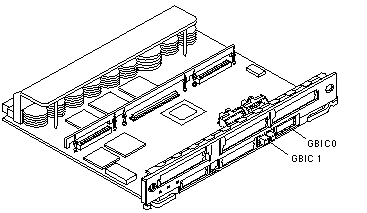
Locate the GBIC to be removed (Figure 4-23 or Figure 4-24).
Figure 4-23 SBus+ I/O Board GBIC Connector Locations
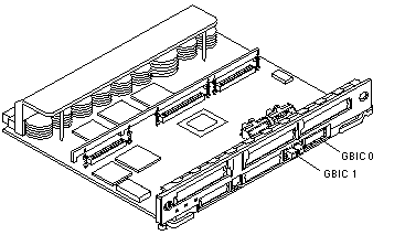
Figure 4-24 Graphics+ I/O Board GBIC Connector Locations
-
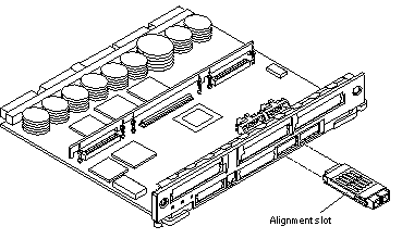
Remove the GBIC from the I/O+ board by compressing the locking tabs located on either side of the card and pulling straight out from the opening in the I/O+ board panel (Figure 4-25).
Figure 4-25 Removing or Installing a GBIC
Installing a GBIC
-
Locate the GBIC slot for installation (Figure 4-24).
-
Ensure correct orientation for insertion.
The alignment slots should be on the bottom of the GBIC (Figure 4-25).
-
Insert the GBIC into the I/O+ board panel slot and then push in to firmly seat the card.
An audible click indicates the GBIC is properly seated to the onboard connector.
PCI Cards
Each PCI+ I/O board can accommodate two PCI (short) cards. The PCI cards are plugged into receptacles on corresponding riser cards that are mounted on the PCI+ I/O board. The riser cards can be one of two voltage types, either 5.0V or 3.3V.
The voltage rating of a PCI card must be matched to the rating of the riser card and connector on the motherboard. The PCI bus connectors of PCI cards can be one of three possible types, those that can be used with 5.0V or 3.3V connector receptacles only, and those that can be used with either voltage type.
Sun PCI+ I/O boards are shipped with two 5.0V riser cards (installed) and two 3.3V riser cards (not installed). If you are switching to a 3.3V PCI card, you must replace the existing 5.0V riser card with the 3.3V riser card. See "Replacing Riser Cards".
Removing a PCI Card
-
Use the procedures in "Removing a Board", to remove the applicable I/O+ board.
Note -Some PCI cards may not utilize the standoffs provided for mounting.
-
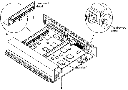
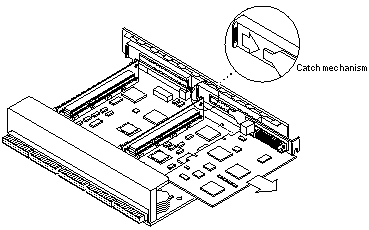
On the noncomponent side of the I/O+ board, loosen the locking standoff for the corresponding PCI card that is to be removed (Figure 4-26).
Figure 4-26 PCI and Riser Card Removal
-
Loosen and then remove the thumbscrew on the component side of the I/O+ board next to the external PCI card connector (Figure 4-26).
-
Refer to Figure 4-27 while removing the card as follows:
-
Grasp the card to be removed with your index fingers on either side of the card where it mates with the connector on the riser card (thumbs against the connector).
-
Loosen the card from the PCI bus connector and the catch mechanism by firmly pushing with your thumbs against the PCI bus connector, while grasping the card edge with the index fingers of both hands.
-
-
Once the card is free of the PCI bus connector and the metal catch mechanism, remove the card from the I/O+ board (Figure 4-27).
Figure 4-27 PCI Card Removal
Replacing or Installing a PCI Card
-
Ensure that the voltage type of the PCI card you are replacing or installing matches the voltage type of the riser card, either 5.0V or 3.3V.
-
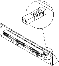
Verify that the JTAG Test Jumper is removed/disabled (Figure 4-28).
Note -PCI+ I/O boards purchased from Sun Microsystems are shipped with the JTAG Test Jumper disabled or removed on both of the 5.0V riser cards installed on the board.
Figure 4-28 JTAG Test Jumper
-
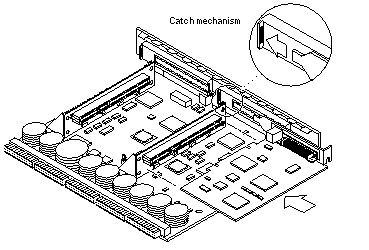
Align the PCI card so that the PCI bus connector mates with the PCI+ I/O board PCI bus connector, making sure that the external connector end of the card is retained on one side by the opening in the metal catch mechanism and the opposite end is properly aligned to accept the locking thumbscrew (Figure 4-29).
Figure 4-29 PCI Card Installation/Replacement
-
Once the card is properly positioned as described above and seated properly to the PCI board PCI Bus connector, tighten the locking thumbscrew.
Note -Some PCI cards may not require the standoffs provided for mounting.
-
Ensure that the standoff is positioned to capture the edge of the PCI card, and then tighten the screw securing the standoff.
-
Use the procedures in the "Installing a Board", to replace the I/O+ board.
Replacing Riser Cards
-
Use the procedures in "Removing a Board", to remove the applicable I/O+ board.
-
If a PCI card is already installed in the slot designated for replacement of the riser card, remove the card as indicated in "Removing a PCI Card".
If there is no PCI card presently installed, proceed to Step 1.
-
Remove two screws securing the existing riser card to the PCI+ I/O board (Figure 4-26) and remove the riser card.
-
Secure the new riser card onto the PCI+ I/O board using the two screws removed in Step 1.
-
If a PCI card was removed in Step 1, replace the card as indicated in the "Replacing or Installing a PCI Card".
Verifying Installation
After the PCI+ I/O board and any PCI cards are installed, and before booting the system, verify installation by performing the following tasks. Refer to the Solaris 2.x Handbook for SMCC Peripherals manual or your Solaris documentation for detailed instructions.
-
Power on the system, and when the banner appears, press the Stop-A keys to interrupt the boot process and get the ok prompt.
-
Use the show-devs command to list the system devices.
You should see entries (similar to the entries in the example below) for the PCI+ I/O board that you installed:
ok show-devs
.
.
.
/pci@3,2000/pci@2
/pci@3,2000/pci@2/SUNW,isptwo@4 (identifies adapter SCSI interface)
/pci@3,2000/pci@2/SUNW,hme@0,1 (identifies adapter Ethernet interface)
/pci@3,2000/pci@2/pci108e,1000@0
/pci@3,2000/pci@2/SUNW,isptwo@4/st
/pci@3,2000/pci@2/SUNW,isptwo@4/sd
/pci@3,4500/SUNW,isptwo@3 (identifies motherboard SCSI interface)
.
.
.
/pci@2,2000/pci@2
/pci@2,2000/pci@2/SUNW,isptwo@4 (identifies adapter SCSI interface)
/pci@2,2000/pci@2/SUNW,hme@0,1 (identifies adapter Ethernet interface)
/pci@2,2000/pci@2/pci108e,1000@0
/pci@2,2000/pci@2/SUNW,isptwo@4/st
/pci@2,2000/pci@2/SUNW,isptwo@4/sd
/pci@2,4500/SUNW,hme@1,1 (identifies motherboard Ethernet interface)
In this example, a PCI+ I/O board with two SunSwift(TM) PCI adapter cards has been installed in I/O+ board slot 1 of an Sun Enterprise 4500 system. To find the device path for your specific device, refer to the documentation that came with your PCI card.
If you do not see your new device(s) listed, make sure the PCI+ I/O board and any PCI cards are properly seated, and reinstall the board or cards, if necessary.
Also verify that the JTAG Test Jumper on the PCI card is disabled or removed.
See "Replacing or Installing a PCI Card".
Flash PROM
The Sun Enterprise 6500/5500/4500 system I/O+ boards use flash PROMs. Flash PROMs may be reprogrammed and can be updated to the latest firmware code. Refer to the Sun Enterprise 6x00/5x00/4x00/3x00 System Flash PROM Programming Guide for this procedure.
Diagnostics Testing
For PCI+ I/O board PCI card diagnostics testing refer to the SunVTS 2.1 User's Guide. Also, refer to the documentation that came with your PCI card for further diagnostic testing.
- © 2010, Oracle Corporation and/or its affiliates
