Clock+ Board
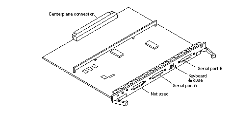
Figure G-25 shows the clock+ board connector locations.
Figure G-25 Clock+ Board Connector Locations

Centerplane Connector
The clock+ board centerplane connector interfaces the board to the system. The connector is divided into six rows of pins labeled A through F; each row has 72 pins.
Figure G-26 Clock+ Board Centerplane Connector Location

Serial Port Connectors
Figure G-27 Clock+ Board Serial Port Connectors Locations

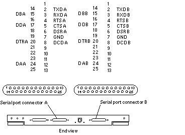
Figure G-28 Serial Port A and B Connector Pinouts

Keyboard and Mouse Connector
Figure G-29 Clock+ Board Keyboard/Mouse Connector Location

Figure G-30 Keyboard and Mouse Connector Pinouts

- © 2010, Oracle Corporation and/or its affiliates
