C H A P T E R  4

Domain Administration Using the Domain Agent

This chapter describes Sun Management Center 3.5 domain administration through the domain agent for Sun Fire Midrange Systems.

This chapter contains the following topics.


Setting Up Administrative Domains

This is a general procedure. For instructions, refer to the Sun Management Center 3.5 User's Guide.


Starting and Stopping Agents

Refer to the Sun Management Center 3.5 User's Guide.


Creating a Node

This is a general procedure. For instructions, refer to the Sun Management Center 3.5 User's Guide.


Config-Reader Module

A Config-Reader module, Config-Reader-Sun Fire(3600-6800), is automatically loaded during installation. You can use the Config-Reader module to see the physical view and logical view of your host.

In addition, the Config-Reader module monitors your hardware and alerts you whenever there is a problem. For example, this module checks for dual inline memory module (DIMM) errors.

The Config-Reader icon is located under the Hardware icon in the Details window (see FIGURE 4-3).


procedure icon  To Use the Config-Reader Module

1. In the Sun Management Center console, double-click a Sun Fire midrange system icon.

The Details window is displayed (FIGURE 4-1).
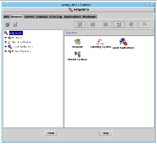
 FIGURE 4-1 Domain Details Window

Screen capture of the domain Details window.

2. Double-click the Hardware icon in the Details window.

The Config-Reader-Sun Fire Midrange Systems and the Sun Fire Midrange Systems Rules icons are displayed (FIGURE 4-2).
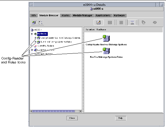
 FIGURE 4-2 Config-Reader and Rules Icons

Screen capture of the Config-Reader and Rules icons in the Browser tab of the Details window.

3. You can now choose either to:

To see the properties and values that are available, see Accessing Tables in the Domain Config-Reader Module. For a list of failures that trigger Config Reader alarms, see Sun Fire Midrange Systems Rules.
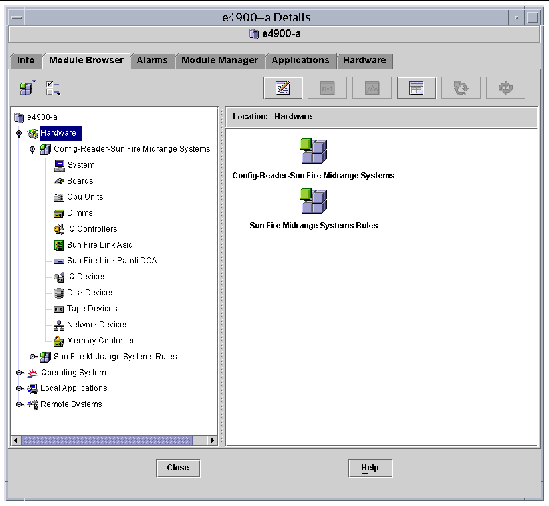
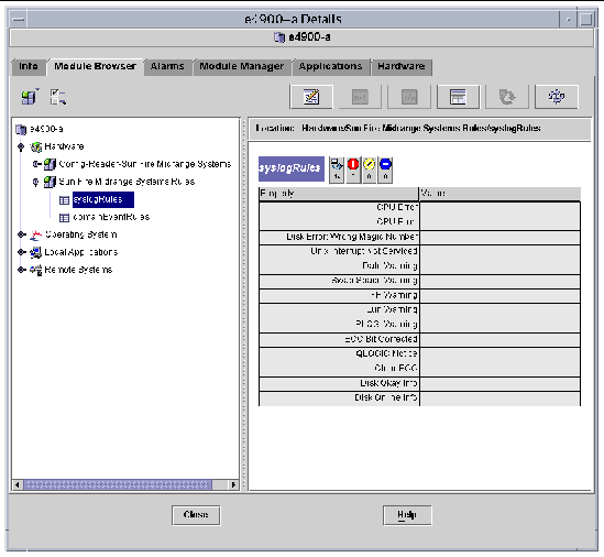
 FIGURE 4-3 Config-Reader Devices

Screen capture of the Config-Reader devices in the Browser tab of the Details window.

 FIGURE 4-4 Sun Fire Midrange Systems Rules Tables

Screen capture of the Sun Fire midrange systems rules tables in the Browser tab of the Details window.

Loading the Config-Reader Module

If the icon for the Config-Reader-Sun Fire Midrange Systems module or the Sun Fire Midrange Systems Rules module is not displayed in the Module Browser tab of the Details window for your Sun Fire Midrange Systems, the corresponding module is not loaded. In that case, you can manually load one or both modules, as shown below.


procedure icon  To Load a Module

1. In the Sun Management Center console, double-click the Sun Fire midrange system icon.

The Details window is displayed (FIGURE 4-1).

2. Click the Module Manager tab in the Details window.

The Module Manager data is displayed (FIGURE 4-5).
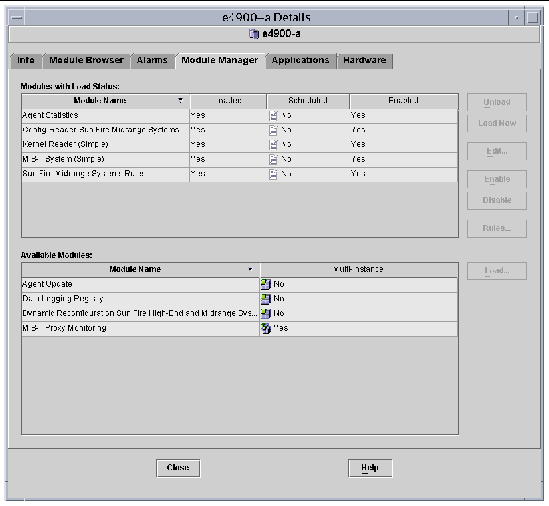
 FIGURE 4-5 Module Manager Tab in the Details Window

Screen capture of the Modules tab of the Details window.

3. Select Config-Reader-Sun Fire Midrange Systems or Sun Fire Midrange Systems Rules in the Available Modules list, then click Load.

The Module Loader pop-up window is displayed.

4. Click OK in the Module Loader pop-up window.

If you have sufficient access privileges, the pop-up window closes, and the module moves into the Modules with Load Status list.

If you do not have sufficient access privileges, the pop-up window displays an error message. See Assigning Users to Groups for information about access privileges.


Accessing Tables in the Domain Config-Reader Module

This section includes the Config-Reader module data property tables:

The following tables describe the data properties contained in each of the domain Config-Reader tables. When selected, the Config-Reader data property tables are displayed in the Module Browser tab of the Details window. For more information, refer to Chapter 7, "Browsing Information About a Managed Object," in the Sun Management Center 3.5 User's Guide.


procedure icon  To Refresh Domain Config-Reader Tables

1. Be sure you have set up trap hosts on your platform and domains. The trap host is the host name of your Sun Management Center server from which you perform platform administration. See Setting Up SNMP on the System Controller for more information.

2. Refresh the System Table (see TABLE 4-1) to refresh all the tables in the Domain Config-Reader module.

Domain System

TABLE 4-1 provides a brief description of the properties for the Sun Fire midrange system that contains the domain.

TABLE 4-1 Domain System

Property

Rule (if any)

Description

Name


Displays the instance name

Operating System


Displays the operating environment running on the machine

Operating System Version


Displays the operating environment version

System Clock Frequency


Displays the clock frequency in megahertz (MHz)

Architecture


Displays the architecture of the machine

Hostname Of The System


Displays the host name of the system

Machine Name


Displays the machine type

System Platform


Displays the hardware platform of the system

Serial Number


Displays the serial number of the machine

Timestamp


Displays the time stamp value

Raw Timestamp


Displays the raw time stamp value

Total Disks


Displays the total number of disks present in the system

Total Memory


Displays the total memory present in the system in megabytes (MB)

Total Processors


Displays the total processors present in the system

Total Tape Devices


Displays the total tape devices present in the system


Domain Boards

TABLE 4-2 provides a brief description of the properties for boards on a Sun Fire Midrange Systems domain.

TABLE 4-2 Domain Boards

Property

Rule (if any)

Description

Name


Displays the system name and slot number for this board, such as board(1), board(3), or board(8)

Label Name


Displays the label name and slot number for this unit, such as system board (SB1 or SB3), or I/O board (IB8)

Board No


Displays the board slot number, such as 1, 3, or 8

Fru


Indicates whether the unit is a field-replaceable unit (yes or no)

Hot Plugged


Indicates whether the board has or has not been hot-plugged into the system (yes or no)

Hot Pluggable


Indicates whether the board is or is not hot-pluggable (yes or no)

Memory Size


Displays the memory size in megabytes (MB)

Condition

rcrse301

Displays the board condition: OK, UNKNOWN, or FAILED

Type


Displays the board type, such as CPU, CPCI_I/O_Bo, PCI_I/O_Boa, or PCI+_I/O_Bo. Includes whether a CPU board is also a COD board (COD_CPU) and whether the board is unknown.


Domain CPU Units

TABLE 4-3 provides a brief description of the properties for CPU units on a Sun Fire Midrange Systems domain.

TABLE 4-3 Domain CPU Units

Property

Rule (if any)

Description

Name


Displays the system name and slot number for this unit, such as cpu-unit(4) or cpu-unit(5)

Board No.


Displays the number of the board where this processor is located

Clock Frequency


Displays the frequency of the timer in megahertz (MHz)

Cpu Type


Displays the processor machine type

Dcache Size


Displays the size of data cache (Dcache) in kilobytes (KB)

Ecache Size


Displays the size of external cache (Ecache) megabytes (MB)

Fru


Indicates whether the unit is a field-replaceable unit (yes or no)

Icache Size


Displays the size of instruction cache (Icache) in kilobytes (KB)

Model


Displays the processor model

Processor Id


Displays the identification number of the processor; or, in the case of a chip multithreading (CMT) processor, displays the processor ID for each core separated by a comma.

Status

rcrse207

Displays the CPU unit status: OK, online, --, noncritical, or offline. In the case of a chip multithreading (CMT) processor, if none of the cores is online, the status is offline. Additionally, if at least one core per processor is online, then the whole processor shows as being online.

Unit


Displays the identification number of the unit


Domain DIMMs

TABLE 4-4 provides a brief description of the properties for dual inline memory modules (DIMMs) on a Sun Fire Midrange Systems domain.

TABLE 4-4 Domain DIMMs

Property

Rule (if any)

Description

Name


Displays the system name and slot number for this unit, such as dimm(0) or dimm(1)

Physical Bank No


Displays the physical bank number where this DIMM is located

Bank Size


Displays the bank size in megabytes (MB)

Bank Status


Displays the operating status: pass, unpopulated, or fail

Fru


Indicates whether the unit is a field-replaceable unit (yes or no)

Dimm Size


Displays the size of the DIMM in megabytes (MB)

Memory Controller


Lists the name of the memory controller for the DIMM (see the property Name in TABLE 4-12)


Domain I/O Controllers

TABLE 4-5 provides a brief description of the properties for I/O controllers on a Sun Fire Midrange Systems domain.

TABLE 4-5 Domain I/O Controllers

Property

Description

Name

Displays the system name and slot number for this unit, such as pcisch(8) or pcisch(9)

Device Type

Displays the device type: pci

Instance Number

Displays the instance number

Model

Displays the device model

Reg

Displays the register address

Portid

Displays the port identifier

Version Number

Displays the version number


Domain Sun Fire Link ASIC

TABLE 4-6 briefly describes the Sun Fire Link ASIC (WCI) properties for a Sun Fire Midrange Systems domain. Refer to the Sun Fire Link Fabric Administrator's Guide for more information about the Sun Fire Link system.

TABLE 4-6 Domain Sun Fire Link ASIC (WCI)

Property

Description

Name

Displays the system name for this unit, such as wci(1d) or wci(1f)

Number of Parolis

Displays the number of Paroli daughter-card assembly (DCA) cards


Domain Sun Fire Link Paroli DCA

TABLE 4-7 briefly describes the Sun Fire Link Paroli daughter card assembly (DCA) properties for a Sun Fire Midrange Systems domain. Refer to the Sun Fire Link Fabric Administrator's Guide for more information about the Sun Fire Link system.


Note - Paroli card presence can be determined only if the domain is part of a Sun Fire Link cluster. If the domain is not part of a Sun Fire Link cluster, the Paroli card table will be empty; however, this is not an indication that there is no Paroli card in the domain.


TABLE 4-7 Domain Sun Fire Link Paroli DCA

Property

Description

Name

Displays the name of the Paroli card, such as paroli(0) or paroli(1)

Fru

Indicates whether the unit is a field-replaceable unit (yes or no)

Link Number

Identifies the port number link to the Paroli card (0 or 2)

Link Validity

Indicates whether the link is VALID or INVALID to the Paroli card

Link State

Displays the current state of the link: LINK UP, LINK DOWN, LINK NOT PRESENT, WAIT FOR SC LINK TAKEDOWN, WAIT FOR SC LINK UP, SC ERROR WAIT FOR LINK DOWN, or UNKNOWN

Remote Link Number

Identifies the link to the remote Paroli card (0-2)

Remote Cluster Member

Displays the host name of the cluster member at the remote end of the link


Domain I/O Devices

TABLE 4-8 provides a brief description of the properties for I/O devices on a Sun Fire Midrange Systems domain.

TABLE 4-8 Domain IO Devices

Property

Description

Name

Displays the system name for this unit

Device Type

Displays the device type

Disk Count

Displays the number of drives attached to this unit

Instance Number

Displays the instance number

Model

Displays the model

Network Count

Displays the number of networks attached to this unit

Reg

Displays the register address

Tape Count

Displays the number of drives attached to this unit


Domain Disk Devices

TABLE 4-9 provides a brief description of the properties for disk devices on a Sun Fire Midrange Systems domain.

TABLE 4-9 Domain Disk Devices

Property

Description

Name

Displays the system name for this unit, such as sd(x), where x is the development index of the disk device

Device Type

Displays the device type, such as disk or CD-ROM

Disk Name

Displays the controller name, such as c110d0 or c210d0

Fru

Indicates whether the unit is a field-replaceable unit (yes or no)

Instance Number

Displays the instance number

Disk Target

Displays the disk target


Domain Tape Devices

TABLE 4-10 provides a brief description of the properties for tape devices on a Sun Fire Midrange Systems domain.

TABLE 4-10 Domain Tape Devices

Property

Rule (if any)

Description

Name


Displays the system name for this unit, such as st(x), where x is the development index of the tape device

Device Type


Displays the device type, such as tape drive

Fru


Indicates whether the unit is a field-replaceable unit (yes or no)

Instance Number


Displays the instance number

Model


Displays the model

Tape Name


Displays the tape name

Status

rcrse225

Displays the operating status, including OK, ok, or drive present, but busy

Tape Target


Displays the tape target number


Domain Network Devices

TABLE 4-11 provides a brief description of the properties for network devices on a Sun Fire Midrange Systems domain.

TABLE 4-11 Domain Network Devices

Property

Description

Name

Displays the system name for this unit, such as hme(5)

Device Type

Displays the device type: network

Ethernet Address

Displays the Ethernet address

Internet Address

Displays the Internet address

Interface Name

Displays the interface name

Symbolic Name

Displays the symbolic name


Domain Memory Controller

TABLE 4-12 provides a brief description of the properties for a memory controller on a Sun Fire Midrange Systems domain.

TABLE 4-12 Domain Memory Controller

Property

Description

Name

Displays the system name for this unit, such as memory-controller(14,400000)

Compatible

Displays compatible software packages

Device Type

Displays the device type: memory-controller

Port Id

Displays the port identifier

Reg

Displays the register address


Domain Config-Reader Rules

This section describes the alarm rules for the domain Config-Reader module. The system provides a message with the alarms telling what the current property is and what the limit is.

CPU Unit Status Rule (rcrse207)

The CPU unit status rule generates a critical alarm when the CPU unit status is not OK, online, --, or noncritical.

TABLE 4-13 Domain Config-Reader CPU Unit Status Rule

Alarm Level

Meaning

Critical

CPU unit is in a critical status.


Action:

Contact your Sun service personnel.

Tape Status Rule (rcrse225)

The tape status rule generates a critical alarm when the tape status is not OK, ok, or drive present, but busy.

TABLE 4-14 Domain Config-Reader Tape Status Rule

Alarm Level

Meaning

Critical

Tape is in a critical status.


Action:

Contact your Sun service personnel.

System Board Condition Rule (rcrse301)

The system board condition rule generates an information alarm when the system board condition is not OK.

TABLE 4-15 Domain Config-Reader System Board Condition Rule

Alarm Level

Meaning

Info

System board condition is not OK.


Action:

This alarm is for your information only; no action is needed.

Attachment Point Status Rule (rLnkVld)

The attachment point status rule generates a information alarm if the state is not VALID.

TABLE 4-16 Domain Config-Reader Attachment Point Status Rule

Alarm Level

Meaning

Info

Attachment point state is not VALID.


Action:

This alarm is for your information only; no action is needed.


Sun Fire Midrange Systems Rules

This section describes the alarm rules for the Sun Fire Midrange Systems. The system provides a message with the alarms telling what the current property is and what the limit is.

CPU Error Message Rule-Solaris 8, 7/01 and Later (rsr1000)

The CPU error message rule generates a critical alarm, when a CPU correctable error is detected. This alarm applies to Solaris 8, 7/01 Operating Environment and later.

TABLE 4-17 CPU Error Message Rule-Solaris 8, 7/01

Alarm Level

Meaning

Critical

CPU correctable error was detected in the /var/adm/messages file.


Action:

Contact your Sun service personnel.

CPU Error Message Rule-Pre-Solaris 8, 7/01 (rsr1001)

The CPU error message rule generates a critical alarm, when a error-correcting code (ECC) memory error is detected. This alarm applies to Operating Environments earlier than Solaris 8, 7/01.

TABLE 4-18 CPU Error Message Rule-Pre-Solaris 8, 7/01

Alarm Level

Meaning

Critical

ECC memory error was detected in the /var/adm/messages file.


Action:

Contact your Sun service personnel.

SCSI Warning Message Rule (rsr1002)

The Small Computer System Interface (SCSI) warning message rule generates a warning alarm when a warning is detected because of an invalid magic number.

TABLE 4-19 SCSI Warning Message Rule

Alarm Level

Meaning

Warning

SCSI warning was detected in the /var/adm/messages file because of an invalid magic number.


Action:

Contact your Sun service personnel.

UNIX Warning Message Rule (rsr1003)

The UNIX warning message rule generates a warning alarm when a warning is detected, because an interrupt has not been serviced.

TABLE 4-20 UNIX Warning Message Rule

Alarm Level

Meaning

Warning

UNIX warning was detected in the /var/adm/messages file because an interrupt has not been serviced.


Action:

Contact your Sun service personnel.

Genunix Date Warning Message Rule (rsr1004)

The Genunix date warning message rule generates a warning alarm when a warning is detected, because the last shutdown time was later than the time on the time-of-day chip.

TABLE 4-21 Genunix Date Warning Message Rule

Alarm Level

Meaning

Warning

Genunix date warning was detected in the /var/adm/messages file, because the last shutdown time was later than the time on the time-of-day chip.


Action:

Contact your Sun service personnel.

Genunix Clock Warning Message Rule (rsr1005)

The Genunix clock warning message rule generates a warning alarm when a warning is detected, because the maximum swap space is less than the free space.

TABLE 4-22 Genunix Clock Warning Message Rule

Alarm Level

Meaning

Warning

Genunix clock warning was detected in the /var/adm/messages file, because the maximum swap space is less than the free space.


Action:

Contact your Sun service personnel.

Fan Plane Warning Message Rule (rsr1006)

The fan plane warning message rule generates a warning alarm when a warning is detected.

TABLE 4-23 Fan Plane Warning Message Rule

Alarm Level

Meaning

Warning

Fan plane warning was detected in the /var/adm/messages file.


Action:

Contact your Sun service personnel.

LUN Failure Rule (rsr1007)

The logical unit number (LUN) failure rule generates a critical alarm when a LUN failure is detected.

TABLE 4-24 LUN Failure Rule

Alarm Level

Meaning

Critical

LUN failure was detected in the /var/adm/messages file.


Action:

Contact your Sun service personnel.

PLOGI Failure Rule (rsr1008)

The PLOGI failure rule generates a critical alarm when a PLOGI failure is detected.

TABLE 4-25 PLOGI Failure Rule

Alarm Level

Meaning

Critical

PLOGI failure was detected in the /var/adm/messages file.


Action:

Contact your Sun service personnel.

ECC Correction Rule (rsr1009)

The ECC correction rule generates an information alarm if the ECC had an error and the ECC data bit has been corrected.

TABLE 4-26 System ECC Correction Rule

Alarm Level

Meaning

Info

ECC data bit is corrected.


Action:

This alarm is for your information only; no action is needed.

Qlogic Error Rule (rsr1010)

The Qlogic error rule generates an alarm when a Qlogic loop error is detected.

TABLE 4-27 Qlogic Error Rule

Value

Alarm Level

Meaning

OFFLINE

Warning

Qlogic loop went offline.

Others

Info

Qlogic loop went online


Action:

Kernel Correction Rule (rsr1011)

The kernel correction rule generates a warning if a clear ECC warning is detected.

TABLE 4-28 Kernel Correction Rule

Alarm Level

Meaning

Warning

Clear ECC warning is detected in the /var/adm/messages file, and the kernel cleared an ECC error.


Action:

Contact your Sun service personnel.

SCSI Info Event Rule (rsr1012)

The SCSI information event rule generates an information alarm when a SCSI information event is detected.

TABLE 4-29 SCSI Info Event Rule

Alarm Level

Meaning

Info

SCSI disk okay and related messages were detected in the /var/adm/messages file.


Action:

This alarm is for your information only; no action is needed.

SCSI Disk Online Rule (rsr1013)

The SCSI disk online rule generates a info alarm when a SCSI disk goes online.

TABLE 4-30 SCSI Disk Online Rule

Alarm Level

Meaning

Info

SCSI disk went online.


Action:

This alarm is for your information only; no action is needed.

Temperature State Rule (rsr1014)

The temperature state rule generates an alarm when the temperature state value is not 1.

TABLE 4-31 Temperature State Rule

Value

Alarm Level

Meaning

1


Temperature state is okay.

2

Warning

Component temperature crosses the warning level.

Others

Critical

Component temperature crosses the error level.


Action:

Contact your Sun service personnel.

Power State Rule (rsr1015)

The power state rule generates an alarm when the power state value is not 1.

TABLE 4-32 System Power State Rule

Value

Alarm Level

Meaning

1


Power state is okay.

2

Warning

Power supply crosses the warning voltage threshold.

Others

Critical

Power supply fails.


Action:

Contact your Sun service personnel.


Physical and Logical Views of a Domain

The Hardware tab in the Details window allows you to view physical and logical hardware configurations of Sun Fire Midrange Systems. For instructions, see Physical View and Logical View of Sun Fire Midrange Systems.

If the system is divided into multiple domains, as a domain administrator you can see detailed information only for domains to which you can access. If you attempt to view a domain to which you do not have access privilege, the message "Insufficient security privilege to load console info" is displayed at the bottom of the Console window.

FIGURE 4-6 shows a physical view of Paroli cards in a domain. Access this view by clicking on the Hardware tab, clicking on the Views list box, and clicking system under Domain. Be sure you have system - Rear in the Rotate Current View list box.
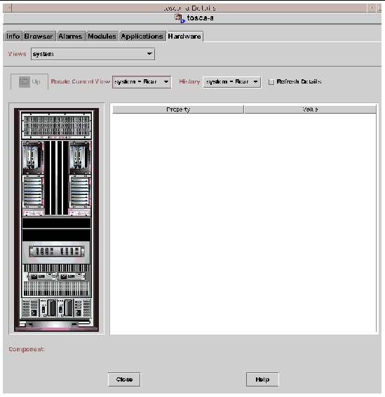
 FIGURE 4-6 Domain Physical View of Paroli Cards (Rear)

Screen capture of a physical view of Paroli cards in a domain.

FIGURE 4-7 shows a physical view of a PCI+ board in a domain. Access this view by clicking on the Hardware tab, clicking on the Views list box, and clicking boards under Domain. Be sure you have system - Rear in the Rotate Current View list box.
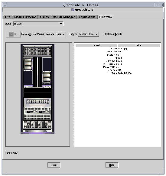
 FIGURE 4-7 Domain Physical View of PCI+ Board (Rear)

Screen capture of a physical view of a PCI+ board in a domain.