Sun Fire 6800/4810/4800/3800 Systems Platform Administration Manual 6800/4810/4800/3800 Systems Platform Administration Manual
|
| Sun Fire 6800/4810/4800/3800 Systems Platform Administration Manual
|
| C H A P T E R 1 |
|
Introduction |
This chapter presents an introduction of features for the family of midframe servers--the Sun Fire 6800/4810/4800/3800 systems. This chapter describes:
The term platform, as used in this book, refers to the collection of resources such as power supplies, the centerplane, and fans that are not for the exclusive use of a domain.
A partition, also referred to as a segment, is a group of Repeater boards that are used together to provide communication between CPU/Memory boards and I/O assemblies in the same domain.
A domain runs its own instance of the Solaris operating environment and is independent of other domains. Each domain has its own CPUs, memory, and I/O assemblies. Hardware resources including fans and power supplies are shared among domains, as necessary for proper operation.
The system controller is an embedded system that connects into the centerplane of these midframe systems. You access the system controller using either serial or Ethernet connections. It is the focal point for platform and domain configuration and management and is used to connect to the domain consoles.
The system controller configures and monitors the hardware in the system and provides a command line interface that enables you to perform tasks needed to configure the platform and each domain. The system controller also provides monitoring and configuration capability with SNMP for use with the Sun Management Center software. For more information on the system controller hardware and software, see System Controller and System Controller Firmware.
With this family of midframe systems, you can group system boards (CPU/Memory boards and I/O assemblies) into domains. Each domain can host its own instance of the Solaris operating environment and is independent of other domains.
Domains include the following features:
All systems are configured at the factory with one domain.
You create domains by using either the system controller command line interface or the Sun Management Center. How to create domains using the system controller software is described in Creating and Starting Domains. For instructions on how to create domains using the Sun Management Center, refer to the Sun Management Center Supplement for Sun Fire 6800/4810/4800/3800 Systems.
The largest domain configuration is comprised of all CPU/Memory boards and I/O assemblies in the system. The smallest domain configuration consists of one CPU/Memory board and one I/O assembly.
An active domain must meet these requirements:
In addition, sufficient power and cooling is required. The power supplies and fan trays are not assigned to a domain.
If you run more than one domain in a partition, then the domains are not completely isolated. A failed Repeater board could affect all domains within the partition. For more information, see Repeater Boards.
|
Note - If a Repeater board failure affects a domain running host-licensed software, it is possible to continue running that software by swapping the HostID/MAC address of the affected domain with that of an available domain. For details, see Swapping Domain HostID/MAC Addresses. |
The system boards in each system consist of CPU/Memory boards and I/O assemblies. The Sun Fire 6800/4810/4800 systems have Repeater boards (TABLE 1-1), which provide communication between CPU/Memory boards and I/O assemblies.
|
Equivalent of two Repeater boards (RP0 and RP2) are built into an active centerplane. |
For a system overview, including descriptions of the boards in the system, refer to the Sun Fire 6800/4810/4800/3800 Systems Overview Manual.
A partition is a group of Repeater boards that are used together to provide communication between CPU/Memory boards and I/O assemblies. Depending on the system configuration, each partition can be used by either one or two domains.
These systems can be configured to have one or two partitions. Partitioning is done at the Repeater board level. A single-mode partition forms one large partition using all of the Repeater boards. In dual-partition mode, two smaller partitions using fewer Repeater boards are created. For more information on Repeater boards, see Repeater Boards.
TABLE 1-2 lists the maximum number of partitions and domains each system can have.
FIGURE 1-1 through FIGURE 1-6 show partitions and domains for the Sun Fire 6800/4810/4800/3800 systems. The Sun Fire 3800 system has the equivalent of two Repeater boards, RP0 and RP2, as part of the active centerplane. The Repeater boards are not installed in the Sun Fire 3800 system as they are for the other systems. Instead, the Repeater boards in the Sun Fire 3800 system are integrated into the centerplane.
All of these systems are very flexible, and you can assign CPU/Memory boards and I/O assemblies to any domain or partition. The configurations shown in the following illustrations are examples only and your configuration may differ.
TABLE 1-3 describes the board names used in FIGURE 1-1 through FIGURE 1-6.
FIGURE 1-1 shows the Sun Fire 6800 system in single-partition mode. This system has four Repeater boards that operate in pairs (RP0, RP1) and (RP2, RP3), six
CPU/Memory boards (SB0 - SB5), and four I/O assemblies (IB6 - IB9).
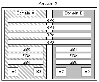
FIGURE 1-2 shows the Sun Fire 6800 system in dual-partition mode. The same boards and assemblies are shown as in FIGURE 1-1.
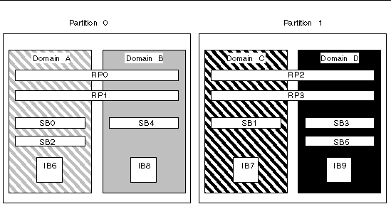
FIGURE 1-3 shows the Sun Fire 4810/4800 systems in single-partition mode. These systems have two Repeater boards (RP0 and RP2) that operate separately (not in pairs as in the Sun Fire 6800 system), three CPU/Memory boards (SB0, SB2, and SB4), and two I/O assemblies (IB6 and IB8).
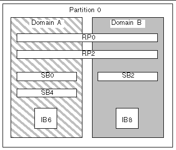
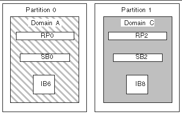
FIGURE 1-4 shows the Sun Fire 4810/4800 systems in dual-partition mode. The same boards and assemblies are shown as in FIGURE 1-3.
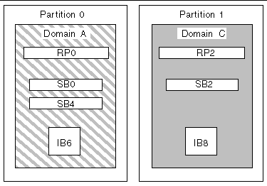
FIGURE 1-5 shows the Sun Fire 3800 system in single-partition mode. This system has the equivalent of two Repeater boards (RP0 and RP2) integrated into the active centerplane, two CPU/Memory boards (SB0 and SB2), and two I/O assemblies
(IB6 and IB8).
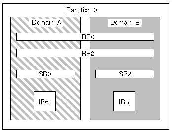
FIGURE 1-6 shows the Sun Fire 3800 system in dual-partition mode. The same boards and assemblies are shown as in FIGURE 1-5. This system also has the equivalent of two Repeater boards, RP0 and RP2, integrated into the active centerplane.
The system controller is an embedded system that connects into the centerplane of the Sun Fire midframe systems. It is the focal point for platform and domain configuration and management and is used to connect to the domain consoles.
System controller functions include:
The system can support up to two System Controller boards (TABLE 1-4) that function as a main and spare system controller. This redundant configuration of system controllers supports the SC failover mechanism, which triggers the automatic switchover of the main SC to the spare if the main SC fails. For details on SC failover, see Chapter 8.
There are two methods to connect to the system controller console:
For performance reasons, it is suggested that the system controllers be configured on a private network. For details, refer to the article, Sun Fire Midframe Server Best Practices for Administration, at
TABLE 1-5 describes the features of the serial port and the Ethernet port on the System Controller board. The Ethernet port provides the fastest connection.
|
Remain in the system controller message queue and are written to the configured syslog host(s). See TABLE 3-1 for instructions on setting up the platform and domain loghosts. Loghosts capture error messages regarding system failures and can be used to troubleshoot system failures. |
||
The system controller supports one logical connection on the serial port and multiple logical connections with telnet on the Ethernet port. Connections can be set up for either the platform or one of the domains. Each domain can have only one logical connection at a time.
The sections that follow provide information on the system controller firmware, including:
The platform administration function manages resources and services that are shared among the domains. With this function, you can determine how resources and services are configured and shared.
Platform administration functions include:
The platform shell is the operating environment for the platform administrator. Only commands that pertain to platform administration are available. To connect to the platform, see Obtaining the Platform Shell.
The platform console is the system controller serial port, where the system controller boot messages and platform log messages are printed.
|
Note - The Solaris operating environment messages are displayed on the domain console. |
When you power on the system, the system controller boots the real time operating system and starts the system controller application.
If there was an interruption of power, additional tasks completed at system power-on include:
The domain administration function manages resources and services for a specific domain.
Domain administration functions include:
For platform administration functions, see Platform Administration.
The domain shell is the operating environment for the domain administrator and is where domain tasks can be performed. There are four domain shells (A - D).
To connect to a domain, see Obtaining a Domain Shell or Console.
If the domain is active (Solaris operating environment, the OpenBoot PROM, or POST is running in the domain), you can access the domain console. When you connect to the domain console, you will be at one of the following modes of operation:
The domains that are available vary with the system type and configuration. For more information on the maximum number of domains you can have, see Partitions.
Each domain has a virtual keyswitch. You can set five keyswitch positions: off (default), standby, on, diag, and secure.
For information on keyswitch settings, see Setting Keyswitch Positions. For a description and syntax of the setkeyswitch command, refer to the Sun Fire 6800/4810/4800/3800 System Controller Command Reference Manual.
Sensors throughout the system monitor temperature, voltage, current, and fan speed. The system controller periodically reads the values from each of these sensors. This information is maintained for display using the console commands and is available to Sun Management Center through SNMP.
When a sensor is generating values that are outside of the normal limits, the system controller takes appropriate action. This includes shutting down components in the system to prevent damage. Domains may be automatically paused as a result. If domains are paused, an abrupt hardware pause occurs (it is not a graceful shutdown of the Solaris operating environment).
The console messages generated by the system controller for the platform and for each domain are printed on the appropriate console. The messages are stored in a buffer on the system controller.
The system controller does not have permanent storage for console messages. Both the platform and each domain have a small buffer that maintains some history. However, this information is lost when the system is rebooted or the system controller loses power.
To enhance accountability and for long-term storage, it is strongly suggested that you set up a syslog host so that the platform and domain console messages are sent to the syslog host. Be aware that these messages are not the Solaris operating environment console messages.
To minimize single points of failure, configure system resources using redundant components, which allows domains to remain functional. Component failures can be quickly and transparently handled when using redundant components.
For troubleshooting tips to perform if a board or component fails, see Board and Component Failures.
This section covers these topics:
You can create two partitions on every midframe system. Use the setupplatform command to set up partition mode. For system controller command syntax and descriptions, refer to the Sun Fire 6800/4810/4800/3800 System Controller Command Reference Manual.
When a system is divided into two partitions, the system controller software logically isolates connections of one partition from the other. Partitioning is done at the Repeater board level. A single partition forms one large partition using all of the Repeater boards. In dual-partition mode, two smaller partitions using fewer Repeater boards are created, each using one-half of the total number of Repeater boards in the system.
Isolating errors to one partition is one of the main reasons to configure your system into dual-partition mode. With two partitions, if there is a failure in one domain in a partition, the failure will not affect the other domains running in the other partition. The exception to this is if there is a centerplane failure.
If you set up two domains, it is strongly suggested that you configure dual-partition mode with the setupplatform command. Each partition should contain one domain.
Be aware that if you configure your system into two partitions, half of the theoretical maximum data bandwidth is available to the domains. However, the snooping address bandwidth is preserved.
The interconnect bus implements cache coherency through a technique called snooping. With this approach each cache monitors the address of all transactions on the system interconnect, watching for transactions that update addresses it possesses. Since all CPUs need to see the broadcast addresses on the system interconnect, the address and command signals arrive simultaneously. The address and command lines are connected in a point-to-point fashion.
Redundancy of a domain means that if one domain fails, the redundant domain can assume all the operations of the failed domain, without interruption.
Redundancy within a domain means that any component in the domain can fail. With redundancy within a domain, when a component in a domain fails, the component failure might not affect domain functionality because the redundant component takes over and continues all operations in the domain.
For I/O, configure redundant paths across I/O assemblies and I/O busses.
|
|
 Keep all devices for a domain in the same power grid.
Unlike the other midframe systems, the Sun Fire 6800 system has two power grids. Each power grid is supplied by a different redundant transfer unit (RTU). TABLE 1-6 lists the boards in power grid 0 and power grid 1.
If you have at least two domains, create domain redundancy using dual-partition mode.
1. Configure dual-partition mode by using setupplatform.
For a command description and syntax, refer to the Sun Fire 6800/4810/4800/3800 System Controller Command Reference Manual.
2. Allocate one domain in each partition.
To eliminate single points of failure, configure system resources using redundant components. This allows domains to remain functional. Component failures can be quickly and transparently handled.
For troubleshooting tips to perform if a board or component fails, see Board and Component Failures.
All systems support multiple CPU/Memory boards. Each domain must contain at least one CPU/Memory board.
The maximum number of CPUs you can have on a CPU/Memory board is four. CPU/Memory boards are configured with either two CPUs or four CPUs. TABLE 1-7 lists the maximum number of CPU/Memory boards for each system.
Each CPU/Memory board has eight physical banks of memory. The CPU provides memory management unit (MMU) support for two banks of memory. Each bank of memory has four slots. The memory modules (DIMMs) must be populated in groups of four to fill a bank. The minimum amount of memory needed to operate a domain is one bank (four DIMMs).
A CPU can be used with no memory installed in any of its banks. A memory bank cannot be used unless the corresponding CPU is installed and functioning.
A failed CPU or faulty memory will be isolated from the domain by the CPU power-on self-test (POST). If a CPU is disabled by POST, the corresponding memory banks for the CPU will also be disabled.
You can operate a domain with as little as one CPU and one memory bank (four memory modules).
All systems support multiple I/O assemblies. For the types of I/O assemblies supported by each system and other technical information, refer to the Sun Fire 6800/4810/4800/3800 Systems Overview Manual. TABLE 1-8 lists the maximum number of I/O assemblies for each system.
There are two possible ways to configure redundant I/O (TABLE 1-9).
The network redundancy features use part of the Solaris operating environment, known as IP multipathing. For information on IP multipathing (IPMP), see IP Multipathing (IPMP) Software and refer to the Solaris documentation supplied with the Solaris 8 or 9 operating environment release.
The Sun StorEdge Traffic Manager provides multipath disk configuration management, failover support, I/O load balancing, and single instance multipath support. For details, refer to the Sun StorEdge documentation available on the Sun Storage Area Network (SAN) Web site:
http://www.sun.com/storage/san
All systems have redundant cooling when the maximum number of fan trays are installed. If one fan tray fails, the remaining fan trays automatically increase speed, thereby enabling the system to continue to operate.

|
Caution - With the minimum number of fan trays installed, you do not have redundant cooling. |
With redundant cooling, you do not need to suspend system operation to replace a failed fan tray. You can hot-swap a fan tray while the system is running, with no interruption to the system.
TABLE 1-10 shows the minimum and maximum number of fan trays required to cool each system For location information, such as the fan tray number, refer to the labels on the system and to the Sun Fire 6800/4810/4800/3800 Systems Service Manual.
Each system has comprehensive temperature monitoring to ensure that there is no over-temperature stressing of components in the event of a cooling failure or high ambient temperature. If there is a cooling failure, the speed of the remaining operational fans increases. If necessary, the system is shut down.
In order for power supplies to be redundant, you must have the required number of power supplies installed plus one additional redundant power supply for each power grid (referred to as the n+1 redundancy model). This means that two power supplies are required for the system to function properly. The third power supply is redundant. All three power supplies draw about the same current.
The power is shared in the power grid. If one power supply in the power grid fails, the remaining power supplies in the same power grid are capable of delivering the maximum power required for the power grid.
If more than one power supply in a power grid fails, there will be insufficient power to support a full load. For guidelines on what to do when a power supply fails, see To Handle Failed Components.
The System Controller boards and the ID board obtain power from any power supply in the system. Fan trays obtain power from either power grid.
TABLE 1-11 describes the minimum and redundant power supply requirements.
|
Total Number of Supplies in Each Power Grid (Including Redundant Power Supplies) |
|||
|---|---|---|---|
Each power grid has power supplies assigned to the power grid. Power supplies ps0, ps1, and ps2 are assigned to power grid 0. Power supplies ps3, ps4, and ps5 are assigned to power grid 1. If one power grid, such as power grid 0 fails, the remaining power grid is still operational.
TABLE 1-12 lists the components in the Sun Fire 6800 system in each power grid. If you have a Sun Fire 4810/4800/3800 system, refer to the components in grid 0, since these systems have only power grid 0.
The Repeater board, also referred to as a Fireplane switch, is a crossbar switch that connects multiple CPU/Memory boards and I/O assemblies. Having the required number of Repeater boards is mandatory for operation. There are Repeater boards in each midframe system except for the Sun Fire 3800. In the Sun Fire 3800 system, the equivalent of two Repeater boards are integrated into the active centerplane. Repeater boards are not fully redundant.
For steps to perform if a Repeater board fails, see Recovering from a Repeater Board Failure. TABLE 1-13 lists the Repeater board assignments by each domain in the Sun Fire 6800 system.
TABLE 1-14 lists the Repeater board assignments by each domain in the Sun Fire 4810/4800 systems.
TABLE 1-15 lists the configurations for single-partition mode and dual-partition mode for the Sun Fire 6800 system regarding Repeater boards and domains.
TABLE 1-16 lists the configurations for single-partition mode and dual-partition mode for the Sun Fire 4810/4800/3800 systems.
The System Controller board provides redundant system clocks. For more information on system clocks, see System Controller Clock Failover.
Reliability, availability, and serviceability (RAS) are features of these midframe systems. The descriptions of these features are:
The following sections provide details on RAS. For more hardware-related information on RAS, refer to the Sun Fire 6800/4810/4800/3800 Systems Service Manual. For RAS features that involve the Solaris operating environment, refer to the Sun Hardware Platform Guide.
The software reliability features include:
The reliability features also improve system availability.
The power-on self-test (POST) is part of powering on a domain. A board or component that fails POST will be disabled. The domain, running the Solaris operating environment, is booted only with components that have passed POST testing.
The physical location of a component, such as slots for CPU/Memory boards or slots for I/O assemblies, can be used to manage hardware resources that are configured into or out of the system.
A component location has either a disabled or enabled state, which is referred to as the component location status.
For example, if you have components that are failing, you can assign the disabled status to the locations of the failed components so that those components are deconfigured from the system.
The component locations that can be specified are described in TABLE 1-17:
Use the following commands to set and review the component location status:
The system controller monitors the system temperature, current, and voltage sensors. The fans are also monitored to make sure they are functioning. Environmental status is not provided to the Solaris operating environment--only the need for an emergency shutdown. The environmental status is provided to the Sun Management Center software with SNMP.
Each system controller provides a system clock signal to each board in the system. Each board automatically determines which clock source to use. Clock failover is the ability to change the clock source from one system controller to another system controller without affecting the active domains.
When a system controller is reset or rebooted, clock failover is temporarily disabled. When the clock source is available again, clock failover is automatically enabled.
Any non-persistent storage device, for example Dynamic Random Access Memory (DRAM) used for main memory or Static Random Access Memory (SRAM) used for caches, is subject to occasional incidences of data loss due to collisions of alpha particles. The data loss changes the value stored in the memory location affected by the collision. These collisions predominantly result in losing one data bit.
When a bit of data is lost, this is referred to as a soft error in contrast to a hard error, which results from faulty hardware. The soft errors happen at the soft error rate, which can be predicted as a function of:
When an error check mechanism detects that one or more bits in a word of data has changed, this is broadly categorized as an error checking and correction (ECC) error. ECC errors can be divided into two classes (TABLE 1-18).
ECC was invented to facilitate the survival of the naturally occurring data losses. Every word of data stored in memory also has check information stored along with it. This check information facilitates two things:
1. When a word of data is read out of memory, the check information can be used to detect:
2. If one bit has changed, the check information can be used to determine which bit in the word changed. The word is corrected by flipping the bit back to its complementary value.
The software availability features include:
Systems with redundant System Controller boards support the SC failover capability. In a high-availability system controller configuration, the SC failover mechanism triggers the switchover of the main SC to the spare if the main SC fails. Within approximately five minutes or less, the spare SC becomes the main and takes over all system controller operations. For details on SC failover, see SC Failover Overview.
When the system controller detects a domain hardware error, it pauses the domain. The firmware includes an auto-diagnosis (AD) engine that tries to identify either the single or multiple components responsible for the error. If possible, the system controller disables (deconfigures) those components so that they cannot be used by the system.
After the auto-diagnosis, the system controller automatically reboots the domain, provided that the reboot-on-error parameter of the setupdomain command parameter is set to true, as part of the auto-restoration process. For details on the AD engine and the auto-restoration process, see Auto-Diagnosis and Auto-Restoration.
An automatic reboot of a specific domain can occur up to a maximum of three times. After the third automatic reboot, the domain is paused if another hardware occurs, and the error reboots are stopped. Rather than restart the domain manually, contact your service provider for assistance on resolving the domain hardware error.
If you set the reboot-on-error parameter to false, the domain is paused when the system controller detects a domain hardware. You must manually restart the domain (perform setkeyswitch off and then setkeyswitch on).
The hang-policy parameter of the setupdomain command, when set to the value reset (default), causes the system controller to automatically recover hung domains. For details, see Automatic Recovery of Hung Domains.
If there is a power outage, the system controller reconfigures active domains. TABLE 1-19 describes domain actions that occur during or after a power failure when the keyswitch is:
|
Processing a keyswitch operation, such as off to on, standby to on, or on to off |
The system controller can be rebooted through SC failover or by using the reboot command, The system controller will start up and resume management of the system. The reboot does not disturb the domain(s) currently running the Solaris operating environment.
The software serviceability features promote the efficiency and timeliness of providing routine as well as emergency service to these systems.
All field-replaceable units (FRUs) that are accessible from outside the system have LEDs that indicate their state. The system controller manages all the LEDs in the system, with the exception of the power supply LEDs, which are managed by the power supplies. For a discussion of LED functions, refer to the appropriate board or device chapter of the Sun Fire 6800/4810/4800/3800 Systems Service Manual.
The system controller, the Solaris operating environment, the power-on self-test (POST), and the OpenBoot PROM error messages use FRU name identifiers that match the physical labels in the system. The only exception is the OpenBoot PROM nomenclature used for I/O devices, which use the device path names as described in Appendix A.
You can configure the system controller platform and domains to log errors by using the syslog protocol to an external loghost. It is strongly recommended that you set the syslog host. For details on setting the syslog host, see TABLE 3-1.
The system controller also has an internal buffer where error messages are stored. You can display the system controller logged events, stored in the system controller message buffer, by using the showlogs command. There is one log for the platform and one log for each of the four domains.
The system controller reset command enables you to recover from a hard hung domain and extract a Solaris operating environment core file.
If a system error occurs due to a fault condition, you can obtain detailed information about the error through the showerrorbuffer command. The information displayed is stored in a system error buffer that retains system error messages. This information can be used by your service provider to analyze a failure or problem.
Capacity on Demand (COD) is an option that provides additional processing resources (CPUs) when you need them. These additional CPUs are provided on COD CPU/Memory boards that are installed in your system. However, to access these COD CPUs, you must first purchase the COD right-to-use (RTU) licenses for them. After you obtain the COD RTU licenses for your COD CPUs, you can activate those CPUs as needed. For details on COD, see COD Overview.
Dynamic reconfiguration (DR), which is provided as part of the Solaris operating environment, enables you to safely add and remove CPU/Memory boards and I/O assemblies while the system is still running. DR controls the software aspects of dynamically changing the hardware used by a domain, with minimal disruption to user processes running in the domain.
You can use DR to do the following:
The DR software uses the cfgadm command, which is a command-line interface for configuration administration. You can perform domain management DR tasks using the system controller software. The DR agent also provides a remote interface to the Sun Management Center software on Sun Fire 6800/4810/4800/3800 systems.
For complete information on DR, refer to the Sun Fire 6800, 4810, 4800, and 3800 Systems Dynamic Reconfiguration User Guide and also the Solaris documentation included with the Solaris operating environment.
The Solaris operating environment implementation of IPMP provides the following features(TABLE 1-20).
For more information on IP network multipathing (IPMP), refer to the System Administration Guide: IP Services, which is available with your Solaris operating environment release. The System Administration Guide: IP Services explains basic IPMP features and network configuration details. This book is available online with your Solaris operating environment release.
The Sun Management Center is the graphical user interface for managing the Sun Fire midframe systems.
To optimize the effectiveness of the Sun Management Center, you must install it on a separate system. The Sun Management Center has the capability to logically group domains and the system controller into a single manageable object, to simplify operations.
The Sun Management Center, once configured, is also the recipient of SNMP traps and events.
To use the Sun Management Center, you must attach the System Controller board to a network. With a network connection, you can view both the command-line interface and the graphical user interface. To attach the System Controller board Ethernet port, refer to the installation documentation that was shipped with your system.
For information on the Sun Management Center, refer to the Sun Management Center Supplement for Sun Fire 6800/4810/4800/3800 Systems, which is available online.
The FrameManager is an LCD that is located in the top right corner of the Sun Fire system cabinet. For a description of its functions, refer to the "FrameManager" chapter of the Sun Fire 6800/4810/4800/3800 Systems Service Manual.
| Sun Fire 6800/4810/4800/3800 Systems Platform Administration Manual
| 817-0999-10 |
Copyright © 2003, Sun Microsystems, Inc. All rights reserved.
