| Sun Management Center 3.5 Version 6 Supplement for Sun Fire Midrange Systems
|
   
|
Dynamic Reconfiguration From the Domain
|
This chapter describes how to perform dynamic reconfiguration (DR) operations from a Sun Fire high-end or midrange systems domain using the Sun Management Center console and the Dynamic Reconfiguration module. The dynamic reconfiguration operations include such operations as attaching a board to a Sun Fire domain, detaching a board from a Sun Fire domain, and configuring a board on a Sun Fire domain. Some other management operations that you might want to perform either as part of a dynamic reconfiguration operation or as part of another operation are testing a board or powering a board off or on.
Prerequisites
You need to be familiar with dynamic reconfiguration operations before you use the Sun Management Center GUI to perform DR operations. Refer to the following documents to learn more about dynamic reconfiguration operations on Sun Fire systems:
- Sun Fire High-End and Midrange Systems Dynamic Reconfiguration User Guide, which describes the underlying operations for the DR module. For the latest general issues, known limitations, and known bugs about dynamic reconfiguration operations for Sun Fire high-end systems, refer to the System Management Services (SMS) Release Notes.
- cfgadm(1M) man page, which describes the underlying command for the DR module.
Dynamic Reconfiguration Module
The Dynamic Reconfiguration module enables you to perform dynamic reconfiguration operations from the domain on the attachment points in the tables. You can perform the operations using the Sun Management Center console in the same manner that you would with the cfgadm(1M) command. This module works on Sun Fire high-end and midrange systems.
During the software installation, this module is automatically installed. You must load this module to use it the first time. You can unload the module, if desired. For specific information about loading and unloading Sun Management Center modules, refer to the Sun Management Center User's Guide.
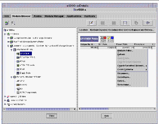
FIGURE 5-1 shows the icon for the module--Dynamic Reconfiguration Sun Fire high-end and midrange systems--as it is displayed in the host Details window on a domain under the Module Browser tab and Hardware icon. FIGURE 5-1 also shows a sample of a DR data table and the DR commands you can use.
FIGURE 5-1 Dynamic Reconfiguration Features
Dynamic Reconfiguration Properties
Use the Dynamic Reconfiguration data tables in the right half of a Details window to find the last-known state of a dynamically reconfigurable board or device.
There are two sections of tables:
- Attachment Points--single attachment points for larger assemblies such as system boards and I/O boards
- Dynamic Attachment Points--dynamic attachment points for individual devices and components such as CPU modules, DIMMs, and SCSI drives
Attachment Points
An attachment point is a collective term for a board and its slot. The Attachment Points tables show information about the following types of board slots:
- CPU/MEM
- IO
- WPCI
- cPCI/hPCI Cards
- SCSI
- Empty Slots
- MaxCPU (Sun Fire high-end systems only)
CPU/MEM
TABLE 5-1 provides a brief description of the attachment point properties for a CPU/memory board.
TABLE 5-1 Attachment Point Properties for a CPU/MEM Board
|
Property
|
Rule (if any)
|
Description
|
|
Unique Ap_Id
|
|
Unique logical attachment point ID from cfgadm: SBx, where x is the number of the centerplane slot containing the board (0-17)
|
|
Slot State
|
|
Slot availability state: assigned or unassigned
|
|
Power State
|
|
Power state: powered-on or powered-off
|
|
Receptacle
|
|
Receptacle state: connected, disconnected, or empty
|
|
Occupant
|
|
State of the occupant, which is the combination of the board and its attached devices: configured or unconfigured
|
|
Type
|
|
Board type: CPU
|
|
Condition
|
|
Board condition: ok, unknown, failed, or unusable
|
|
Information
|
|
General board type information; for example, powered-on, assigned
|
|
When
|
|
Date and time when the board was configured into the domain
|
|
Busy
|
|
y (yes) indicates a state, availability, or condition change operation is in progress; n (no) indicates no state, availability, or condition change operation is in progress
|
|
Phys_Id
|
|
Physical attachment point ID: /devices/pseudo/dr@0:SBx, where x is the number of the centerplane slot containing the board (0-17)
|
Table listing attachment point properties for a CPU/Memory board, with their descriptions. I/O Boards
TABLE 5-2 provides a brief description of the attachment point properties for I/O boards. For Sun Fire midrange systems, the table shows properties only for PCI, PCI+, and cPCI I/O boards.
TABLE 5-2 Attachment Point Properties for I/O Boards
|
Property
|
Rule (if any)
|
Description
|
|
Unique Ap_Id
|
|
Unique logical attachment point ID from cfgadm: IOx, where x is the number of the centerplane slot containing the board (0-17)
|
|
Slot State
|
|
Slot availability state: assigned or unassigned
|
|
Power State
|
|
Power state: powered-on or powered-off
|
|
Receptacle
|
|
Receptacle state: connected, disconnected, or empty
|
|
Occupant
|
|
State of the occupant, which is the combination of the board and its attached devices: configured or unconfigured
|
|
Type
|
|
Board type, such as PCI_I/O_Boa, PCI+_I/O_Bo, HPCI, or HPCI+
|
|
Condition
|
|
Board condition: ok, unknown, failed, or unusable
|
|
Information
|
|
General board type information; for example, powered-on, assigned
|
|
When
|
|
Date and time when the board was configured into the domain
|
|
Busy
|
|
y (yes) indicates a state, availability, or condition change operation is in progress; n (no) indicates no state, availability, or condition change operation is in progress
|
|
Phys_Id
|
|
Physical attachment point ID: /devices/pseudo/dr/@0:IOx, where x is the number of the centerplane slot containing the board (0-17)
|
Table listing attachment point properties for a PCI/PCI+/cPCI/hPCI IO board, with their descriptions. WPCI
TABLE 5-3 provides a brief description of the attachment point properties for a WPCI board. Refer to the Sun Fire Link Fabric Administrator's Guide for more information about the Sun Fire Link system.
TABLE 5-3 Attachment Point Properties for a WPCI Board
|
Property
|
Rule (if any)
|
Description
|
|
Unique Ap_Id
|
|
Unique logical attachment point ID from cfgadm: IOx, where x is the number of the centerplane slot containing the board (0-17)
|
|
Slot State
|
|
Slot availability state: assigned or unassigned
|
|
Power State
|
|
Power state: powered-on or powered-off
|
|
Receptacle
|
|
Receptacle state: connected, disconnected, or empty
|
|
Occupant
|
|
State of the occupant, which is the combination of the board and its attached devices: configured or unconfigured
|
|
Type
|
|
Board type: WPCI
|
|
Condition
|
|
Board condition: ok, unknown, failed, or unusable
|
|
Information
|
|
General board type information; for example, powered-on, assigned
|
|
When
|
|
Date and time when the board was configured into the domain
|
|
Busy
|
|
y (yes) indicates a state, availability, or condition change operation is in progress; n (no) indicates no state, availability, or condition change operation is in progress
|
|
Phys_Id
|
|
Physical attachment point ID: /devices/pseudo/dr/@0:IOx, where x is the number of the centerplane slot containing the board (0-17)
|
Table listing attachment point properties for a WPCI board with their descriptions. cPCI/hPCI Cards
TABLE 5-4 provides a brief description of the attachment point properties for the cPCI or hPCI card. For Sun Fire midrange systems, the table shows properties only for cPCI cards. For Sun Fire high-end systems, the table shows properties only for hPCI cards.
|
Note - A SCSI card is also considered to be a cPCI/hPCI card by the system. Configured SCSI cards appear in two tables in the DR module: the SCSI table and the cPCI/hPCI table. When the SCSI card is unconfigured, it only appears in the cPCI/hPCI table, because at that point the card type is unknown to the system.
|
TABLE 5-4 Attachment Point Properties for a cPCI/hPCI Card
|
Property
|
Rule (if any)
|
Description
|
|
Unique Ap_Id
|
|
Unique logical attachment point ID from cfgadm, such as pci_pci0:e05b1slot0 or pcisch2:e04b1slot3
|
|
Slot State
|
|
Slot availability state: assigned or unassigned
|
|
Power State
|
|
Power state: powered-on or powered-off
|
|
Receptacle
|
|
Receptacle state: connected, disconnected, or empty
|
|
Occupant
|
|
State of the occupant, which is the combination of the board and its attached devices: configured or unconfigured
|
|
Type
|
|
Type, such as pci-pci/hp
|
|
Condition
|
|
Board condition: ok, unknown, failed, or unusable
|
|
Information
|
|
General information; for example, unknown
|
|
When
|
|
Date and time when the board was configured into the domain
|
|
Busy
|
|
y (yes) indicates a state, availability, or condition change operation is in progress; n (no) indicates no state, availability, or condition change operation is in progress
|
|
Phys_Id
|
|
Physical attachment point ID, such as /devices/pci@9d,7000000:e04b1slot3
|
Table listing attachment point properties for a cPCI/hPCI card with their descriptions. SCSI
TABLE 5-5 provides a brief description of the attachment point properties for a SCSI card.
|
Note - When you unconfigure a SCSI card from this SCSI table, you no longer see the card entry in the table. A SCSI card is also considered to be a cPCI/hPCI card by the system, and configured SCSI cards appear in two tables in the DR module: the SCSI table and the cPCI/hPCI table. When the card is unconfigured, it only appears in the cPCI/hPCI table, because at that point the card type is unknown to the system.
|
TABLE 5-5 Attachment Point Properties for a SCS CardI
|
Property
|
Rule (if any)
|
Description
|
|
Unique Ap_Id
|
|
Unique logical attachment point ID from cfgadm, such as pcisch3:e04b1slot2
|
|
Slot State
|
|
Slot availability state: assigned or unassigned
|
|
Power State
|
|
Power state: powered-on or powered-off
|
|
Receptacle
|
|
Receptacle state: connected, disconnected, or empty
|
|
Occupant
|
|
State of the occupant, which is the combination of the board and its attached devices: configured or unconfigured
|
|
Type
|
|
Type, such as scsi/hp
|
|
Condition
|
|
Component condition: ok, unknown, failed, or unusable
|
|
Information
|
|
General component information, such as unknown
|
|
When
|
|
Date and time when the component was configured into the domain
|
|
Busy
|
|
y (yes) indicates a state, availability, or condition change operation is in progress; n (no) indicates no state, availability, or condition change operation is in progress
|
|
Phys_Id
|
|
Physical attachment point ID, such as /devices/pci@9d,600000:e04b1slot2
|
Table listing attachment point properties for a SCSI, with their descriptions. Empty Slots
TABLE 5-6 provides a brief description of the attachment point properties for empty slots.
TABLE 5-6 Attachment Point Properties for Empty Slots
|
Property
|
Rule (if any)
|
Description
|
|
Unique Ap_Id
|
|
Unique logical attachment point ID from cfgadm, such as pcisch0:e17b1slot1
|
|
Slot State
|
|
Slot availability state: assigned or unassigned
|
|
Power State
|
|
Power state: powered-on or powered-off
|
|
Receptacle
|
|
Receptacle state: connected, disconnected, or empty
|
|
Occupant
|
|
State of the occupant, which is the combination of the board and its attached devices: configured or unconfigured
|
|
Type
|
|
Board type: unknown
|
|
Condition
|
|
Component condition: ok, unknown, failed, or unusable
|
|
Information
|
|
General board type information: assigned or unknown
|
|
When
|
|
Date and time when the slot was configured into the domain
|
|
Busy
|
|
n (no) indicates no state, availability, or condition change operation is in progress
|
|
Phys_Id
|
|
Physical attachment point ID, such as /devices/pci@9d,6000000:e17b1slot1
|
Table listing attachment point properties for empty slots, with their descriptions. MaxCPU
TABLE 5-7 provides a brief description of the attachment point properties for a MaxCPU board. This table appears only for Sun Fire high-end systems.
TABLE 5-7 Attachment Point Properties for MaxCPU Board on Sun Fire High-End Systems
|
Property
|
Rule (if any)
|
Description
|
|
Unique Ap_Id
|
|
Unique logical attachment point ID from cfgadm for the MaxCPU board
|
|
Slot State
|
|
Slot availability state: assigned or unassigned
|
|
Power State
|
|
Power state: powered-on or powered-off
|
|
Receptacle
|
|
Receptacle state: connected, disconnected, or empty
|
|
Occupant
|
|
State of the occupant, which is the combination of the board and its attached devices: configured or unconfigured
|
|
Type
|
|
Board type: MCPU
|
|
Condition
|
|
Board condition: ok, unknown, failed, or unusable
|
|
Information
|
|
General board type information; for example, powered-on, assigned
|
|
When
|
|
Date and time when the board was configured into the domain
|
|
Busy
|
|
y (yes) indicates a state, availability, or condition change operation is in progress; n (no) indicates no state, availability, or condition change operation is in progress
|
|
Phys_Id
|
|
Physical attachment point ID for the MaxCPU board
|
Table listing attachment point properties for a MaxCPU board, with their descriptions. Dynamic Attachment Points
Dynamic attachment points refer to components on the system boards, such as CPUs, memory, and I/O devices. The dynamic attachment points are created by the DR driver. Refer to the dr(7D) man page in the Sun Solaris Reference Manual Collection for more details about the DR driver. The Dynamic Attachment Point tables show information about the following types of components:
- CPU
- Memory
- I/O
- SCSI Components
CPU Components
TABLE 5-7 provides a brief description of the dynamic attachment point properties for CPU components.
TABLE 5-8 Dynamic Attachment Point Properties for CPU Components
|
Property
|
Rule (if any)
|
Description
|
|
Unique Ap_Id
|
|
Unique logical attachment point identifier from cfgadm: SBx::cpuy, where x is the number of the centerplane slot containing the board (0-17) and y is the CPU number (0-3)
|
|
Slot State
|
|
Slot availability state: assigned or unassigned
|
|
Power State
|
|
Power state: powered-on or powered-off
|
|
Receptacle
|
|
Receptacle state: connected
|
|
Occupant
|
|
State of the occupant, which is the combination of the board and its attached devices: configured or unconfigured
|
|
Type
|
|
Component type: cpu
|
|
Condition
|
|
Component condition: ok, unknown, or failed
|
|
Information
|
|
General CPU type information: for example, cpuid 2, speed 750 MHz, ecache 8 MBytes. Refer to the cfgadm_sbd(1M) man page in the Solaris Reference Manual Collection for descriptions of the fields.
|
|
When
|
|
Date and time when the components were configured into the domain
|
|
Busy
|
|
y (yes) indicates a state, availability, or condition change operation is in progress; n (no) indicates no state, availability, or condition change operation is in progress
|
|
Phys_Id
|
|
Physical attachment point ID: /devices/pseudo/dr@0:SBx::cpuy, where x is the number of the centerplane slot containing the board (0-17), and y is the CPU number (0-3)
|
Table listing dynamic attachment point properties for CPU components, with their descriptions. Memory Components
TABLE 5-9 provides a brief description of the dynamic attachment point properties for memory components.
TABLE 5-9 Dynamic Attachment Point Properties for Memory Components
|
Property
|
Rule (if any)
|
Description
|
|
Unique Ap_Id
|
|
Unique logical attachment point identifier from cfgadm: such as SBx::memory, where x is the number of the centerplane slot containing the board (0-17)
|
|
Slot State
|
|
Slot availability state: assigned or unassigned
|
|
Power State
|
|
Power state: powered-on or powered-off
|
|
Receptacle
|
|
Receptacle state: connected
|
|
Occupant
|
|
State of the occupant, which is the combination of the board and its attached devices: unconfigured or configured
|
|
Type
|
|
Component type: memory
|
|
Condition
|
|
Component condition: ok, unknown, or failed
|
|
Information
|
|
General information for the memory type, as appropriate; for example, base address 0x0, 2097 152 KBytes total, 420920 KBytes permanent. Refer to the cfgadm_sbd(1M) man page in the Solaris Reference Manual Collection for descriptions of the fields.
|
|
When
|
|
Date and time when the components were configured into the domain
|
|
Busy
|
|
y (yes) indicates a state, availability, or condition change operation is in progress; n (no) indicates no state, availability, or condition change operation is in progress
|
|
Phys_Id
|
|
Physical attachment point ID: /devices/pseudo/dr@0:SBx::memory, where x is the number of the centerplane slot containing the board (0-17)
|
Table listing dynamic attachment point properties for memory components, with their descriptions. I/O Components
TABLE 5-10 provides a brief description of the dynamic attachment point properties for I/O components.
TABLE 5-10 Dynamic Attachment Point Properties for I/O Components
|
Property
|
Rule (if any)
|
Description
|
|
Unique Ap_Id
|
|
Unique logical attachment point identifier from cfgadm: NO.IBx::pciy, where x is the number of the centerplane slot containing the board (0-17) and y is the PCI number (0-3)
|
|
Slot State
|
|
Slot availability state: assigned or unassigned
|
|
Power State
|
|
Power state: powered-on or powered-off
|
|
Receptacle
|
|
Receptacle state: connected
|
|
Occupant
|
|
State of the occupant, which is the combination of the board and its attached devices: configured or unconfigured
|
|
Type
|
|
Component type: io
|
|
Condition
|
|
Component condition: ok, unknown, or failed
|
|
Information
|
|
General information for the io type; for example, device/pci@23d,700000 referenced. Refer to the cfgadm_sbd(1M) man page in the Solaris Reference Manual Collection for descriptions of the fields.
|
|
When
|
|
Date and time when the components were configured into the domain
|
|
Busy
|
|
y (yes) indicates a state, availability, or condition change operation is in progress; n (no) indicates no state, availability, or condition change operation is in progress
|
|
Phys_Id
|
|
Physical attachment point ID: /devices/pseudo/dr@0:IOx::pciy, where x is the number of the centerplane slot containing the board (0-17) and y is the PCI number (0-3)
|
Table listing dynamic attachment point properties for I/O components, with their descriptions. SCSI Components
TABLE 5-11 provides a brief description of the dynamic attachment point properties for SCSI components,
TABLE 5-11 Dynamic Attachment Point Properties for SCSI Components
|
Property
|
Rule (if any)
|
Description
|
|
Unique Ap_Id
|
|
Unique logical attachment point identifier from cfgadm for the SCSI component
|
|
Slot State
|
|
Slot availability state: assigned or unassigned
|
|
Power State
|
|
Power state: powered-on or powered-off
|
|
Receptacle
|
|
Receptacle state: connected
|
|
Occupant
|
|
State of the occupant, which is the combination of the board and its attached devices: configured or unconfigured
|
|
Type
|
|
Component type: disk, CD-ROM, or tape
|
|
Condition
|
|
Component condition: ok, unknown, or failed
|
|
Information
|
|
General information for the type
|
|
When
|
|
Date and time when the components were configured into the domain
|
|
Busy
|
|
y (yes) indicates a state, availability, or condition change operation is in progress; n (no) indicates no state, availability, or condition change operation is in progress
|
|
Phys_Id
|
|
Physical attachment point ID for the SCSI component
|
Table listing dynamic attachment point properties for SCSI components, with their descriptions.
Dynamic Reconfiguration Operations From the Domain
This section describes how to perform dynamic reconfiguration operations from a Sun Fire domain using the Sun Management Center Dynamic Reconfiguration module. The dynamic reconfiguration operations from the domain are based on the cfgadm(1M) command. Refer to the cfgadm(1M) command in the Sun Solaris Reference Manual Collection for more information about the various cfgadm options.
There are both logical and physical aspects of Sun Fire domains:
- The logical domain is the set of slots--either containing or not containing system boards--grouped as belonging to a specific domain.
- The physical domain is the set of boards in the logical domain that are physically interconnected.
A slot--whether occupied or empty--can be a member of a logical domain, while not being part of a physical domain. After boot, a board or empty slot can be assigned to or unassigned from a logical domain. A board becomes part of a physical domain when the Solaris Operating System requests it. An empty slot is never part of a physical domain.
The following dynamic reconfiguration and other management operations from the domain are described in this section of the supplement:
- Assigning a board
- Unassigning a board
- Attaching a board
- Detaching a board
- Connecting a board
- Disconnecting a board
- Configuring a board or components
- Unconfiguring a board, components, or memory
- Powering on a board
- Powering off a board
- Testing a board
- Showing status
cfgadm Options Supported
TABLE 5-12 describes the cfgadm(1M) options that are supported by the Dynamic Reconfiguration module. Refer to the cfgadm(1M) command in the Sun Solaris Reference Manual Collection for more information about the various cfgadm options.
TABLE 5-12 cfgadm Options Supported by Dynamic Reconfiguration
|
cfgadm Option
|
Sun Management Center GUI Menu Item
|
Description
|
|
-c configure
|
Attach
|
Attach a board
|
|
-c disconnect
|
Detach
|
Detach a board
|
|
-x assign
|
Assign
|
Assign a board
|
|
-c disconnect
-x unassign
|
Unassign
|
Unassign a board
|
|
-c connect
|
Connect
|
Connect a board
|
|
-c disconnect
|
Disconnect
|
Disconnect a board
|
|
-c configure
|
Configure
|
Configure a board or another component
|
|
-c unconfigure
|
Unconfigure
|
Unconfigure a board or another component
|
|
-x poweron
|
Power On
|
Power on a board
|
|
-x poweroff
|
Power Off
|
Power off a board
|
|
-t
|
Test
|
Test a board
|
Table listing cfgadm options supported by the Dynamic Reconfiguration model, with their associated Sun Management Center GUI menu items and descriptions.
|
Note - Before you perform any dynamic reconfiguration operations from a Sun Fire domain, look at the Attachment Points and Dynamic Attachment Points tables in the Dynamic Reconfiguration module under Hardware.
|
|
Note - Before you can perform certain dynamic reconfiguration operations on a system board from a domain, the board must be in the domain's ACL.
|
Assigning a Board
This operation adds a system board to the logical domain.
 To Assign a Board To Assign a Board
|
1. Log in as a member of the esadm group to the domain to which you want to assign a system board.
2. Right-click on the Unique Ap_Id for the system board you want to assign in the appropriate board table.
The system displays a menu of board operations.
3. Choose Assign.
The system displays the Assign confirmation box with this message:
Assign a slot.
Are you sure you want to assign?
|
4. Click the OK button to assign the selected board.
Unassigning a Board
This operation removes a system board from the logical domain.
 To Unassign a Board To Unassign a Board
|
1. Log in as a member of the esadm group to the domain from which you want to unassign a system board.
2. Right-click the Unique Ap_Id for the system board you want to unassign in the appropriate board table.
The system displays a menu of board operations.
3. Choose Unassign.
The system displays the Unassign confirmation box with this message:
Unassign.
Are you sure you want to unassign?
|
4. Click the OK button to unassign the selected board.
Attaching a System Board
This operation attaches the specified system board to the Solaris Operating System running in the specified domain. The process of attaching a system board involves a series of automatic steps performed by the Dynamic Reconfiguration module:
- Assigning the system board to the logical domain
- Powering on the system board
- Testing the system board
- Connecting the system board to the domain physically through the system controller
- Configuring the components on the system board in the Solaris Operating System running on the domain, so that applications running on the domain can use the components
Which of the automatic steps are performed depends on the initial state of the system board and other components, as well as on whether hardware problems prohibit the successful completion of the attach operation.
 To Attach a System Board To Attach a System Board
|
1. Log in as a member of the esadm group to the domain to which you want to attach a system board.
2. Right-click on the Unique Ap_Id for the system board you want to attach in the appropriate board table.
The system displays a menu of board operations.
3. Choose Attach .
The system displays the Attach Confirmation box with this message:
Attach a board.
Attach will connect and configure the selected board.
Are you sure you want to attach?
|
4. Click the OK button to connect and configure the selected board.
Detaching a System Board
This operation detaches the specified system board from the Solaris Operating System running in the specified domain. The process of detaching a system board involves a series of automatic steps performed by the Dynamic Reconfiguration module:
- Unconfiguring the components on the system board from the Solaris Operating System running on the domain, so that applications running on the domain can no longer use the components.
- Communicating with the system controller to physically disconnect the system board from the domain. After this step, the system board is no longer part of the physical domain, although it is still part of the logical domain.
- Powering off the system board.
Which of the automatic steps are performed depends on the initial state of the system board and other components, as well as on whether hardware problems prohibit the successful completion of the detach operation.
 To Detach a System Board To Detach a System Board
|
1. Log in as a member of the esadm group to the domain from which you want to detach a system board.
2. Right-click on the Unique Ap_Id for the system board you want to detach in the appropriate board table.
The system displays a menu of board operations.
3. Choose Detach.
The system displays the Detach confirmation box (FIGURE 5-2).
FIGURE 5-2 Detach Confirmation Box
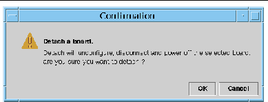
4. Click the OK button to unconfigure, disconnect, and power off the selected board.
Connecting a Board
This operation performs the following steps:
- Assigning the system board to a logical domain if the board is available and is not part of the logical domain
- Powering on the system board
- Testing the system board
- Connecting the system board to the physical domain
 To Connect a System Board To Connect a System Board
|
1. Log in as a member of the esadm group to the domain in which you want to connect a system board.
2. Right-click on the Unique Ap_Id for the system board you want to connect in the appropriate board table.
The system displays a menu of board operations.
3. Choose Connect.
The system displays the Connect confirmation box with this message:
Connect
Are you sure you want to connect?
|
4. Click the OK button to connect the selected board.
|
Note - Sun Fire high-end systems allow you to click an Abort button to stop the operation prematurely.
|
Disconnecting a Board
This operation performs the following steps:
- Unconfigures the system board, if necessary
- Disconnects the system board from the physical domain
 To Disconnect a System Board Other Than a SCSI Board To Disconnect a System Board Other Than a SCSI Board
|
1. Log in as a member of the esadm group to the domain in which you want to disconnect a system board.
2. Right-click on the Unique Ap_Id for the system board you want to disconnect in the appropriate board table.
The system displays a menu of board operations.
3. Choose Disconnect.
The system displays the Disconnect panel (FIGURE 5-3).
FIGURE 5-3 Disconnect Panel
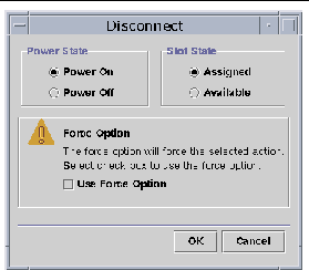
4. Select the Power State option you want the board to be in after it is disconnected.
5. Select the Slot State option you want the board to be in after it is disconnected.
6. Select the Use Force Option to force the disconnect operation. Otherwise, leave the Use Force Option box blank.
7. Click the OK button to disconnect the selected board.
|
Note - Sun Fire high-end systems allow you to click an Abort button to stop the operation prematurely.
|
 To Disconnect a SCSI Board To Disconnect a SCSI Board
|
Log in as a member of the esadm group to the domain in which you want to disconnect a SCSI board.
1. Right-click on the Unique Ap_Id for the SCSI board you want to disconnect in the appropriate board table.
The system displays a menu of board operations.
2. Choose Disconnect.
The system displays the Disconnect panel with this message:
Disconnect
Are you sure you want to continue?
|
3. Click the OK button to disconnect the SCSI board.
Configuring a Board, a Component, or Memory
This operation performs the following steps:
- Connects the system board, if necessary.
- Configures a system board or a component or memory on a board into the Solaris Operating System running in the domain, so that applications running on the domain can use the board or the component or memory on the board.
 To Configure a System Board, a Component, or Memory To Configure a System Board, a Component, or Memory
|
1. Log in as a member of the esadm group to the domain in which you want to configure a system board, a component, or memory.
2. Right-click on the Unique Ap_Id for the system board, component, or memory you want to configure in the appropriate board table.
The system displays a menu of board, component, or memory operations.
3. Choose Configure.
The system displays the Configure confirmation box with this message:
Configure
Are you sure you want to configure?
|
4. Click the OK button to configure the selected board, component, or memory.
|
Note - Sun Fire high-end systems allow you to click an Abort button to stop the operation prematurely.
|
Unconfiguring a Board, a Component, or Memory
This operation unconfigures a system board, a component on a board, or memory so that applications running on the domain can no longer use the board, component, or memory.
 To Unconfigure a System Board or a Component To Unconfigure a System Board or a Component
|
1. Log in as a member of the esadm group to the domain in which you want to unconfigure a system board or component.
2. Right-click on the Unique Ap_Id for the system board or component you want to unconfigure in the appropriate board table.
The system displays a menu of board or component operations.
3. Choose Unconfigure.
The system displays the Unconfigure panel with this message:
Select Force Option
The force option will force the selected action.
Select check box to use the force option.
|
4. Click Use Force Option check box to force the unconfigure operation. Otherwise, leave the Use Force Option box blank.
5. Click the OK button to unconfigure the selected board or component.
|
Note - Sun Fire high-end systems allow you to click an Abort button to stop the operation prematurely.
|
 To Unconfigure Memory To Unconfigure Memory
|
1. Log in as a member of the esadm group to the domain in which you want to unconfigure memory.
2. Right-click on the Unique Ap_Id for the memory component you want to unconfigure in the Memory component table.
The system displays a menu of memory component operations.
3. Choose Unconfigure.
The system displays the Unconfigure Memory panel (FIGURE 5-4).
FIGURE 5-4 Unconfigure Memory Panel
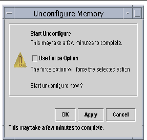
4. (Optional) Click the Use Force Option box to force the unconfigure operation.
5. Click the OK button to start unconfiguring memory.
Powering on a Board
This operation powers on a system board. The board must be assigned to the logical domain, but not be in the physical domain.
 To Power on a Board To Power on a Board
|
1. Log in as a member of the esadm group to the domain in which you want to power on a system board.
2. Right-click on the Unique Ap_Id for the system board you want to power on in the appropriate board table.
The system displays a menu of board operations.
3. Choose Power On.
The system displays the Power On confirmation box with this message:
Power On a board.
Are you sure you want to power on?
|
4. Click the OK button to power on a system board.
Powering off a Board
This operation powers off a system board. The board must be assigned to the logical domain, but not be in the physical domain.
 To Power off a Board To Power off a Board
|
1. Log in as a member of the esadm group to the domain in which you want to power off a system board.
2. Right-click on the Unique Ap_Id for the system board you want to power off in the appropriate board table.
The system displays a menu of board operations.
3. Choose Power Off.
The system displays the Power Off confirmation box with this message:
Power Off a board.
Are you sure you want to power off?
|
4. Click the OK button to power off a system board.
Testing a Board
This operation tests system boards. The board must be assigned to the logical domain, but not be in the physical domain.
 To Test a Board To Test a Board
|
1. Log in as a member of the esadm group to the domain in which you want to test a system board.
2. Right-click on the Unique Ap_Id for the system board you want to test in the appropriate board table.
The system displays a menu of board operations.
3. Choose Test.
The system displays the Test Board panel (FIGURE 5-5).
FIGURE 5-5 Test Board Panel
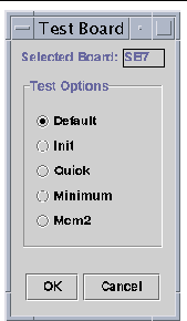
4. Select the radio button beside the Test Option you want.
5. After ensuring that you have selected the correct board to test and have the correct option checked, click the OK button to start the test.
|
Note - Sun Fire high-end systems allow you to click an Abort button to stop the operation prematurely.
|
Showing Status
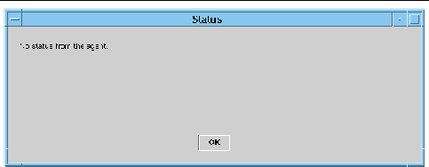
This operation shows the status of the last dynamic reconfiguration command executed for that board or slot. The status display is dynamically updated with the status of the command currently being executed. If the command being executed halts on an error, an error message from the cfgadm(1M) program is displayed. The message "No status from the agent" is displayed if no command has been executed, or if a command finishes execution without errors.
 To Show Status To Show Status
|
1. Log in as a member of the esadm group to the domain in which you want to show status for a system board or slot.
2. Right-click on the Unique Ap_Id for the system board or slot for which you want to show status in the appropriate board table.
The system displays a menu of board or slot operations.
3. Choose Show Status.
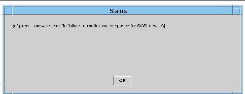
The system displays the Status box showing the execution status of the most current dynamic reconfiguration command, if any.
For example, if an operation fails, the status shows this type of message (FIGURE 5-6):
FIGURE 5-6 Unsuccessful Domain DR Operation in Show Status
The status shows this message after the configure operation finishes successfully or if no command has been executed (FIGURE 5-7):
FIGURE 5-7 Successful Domain DR Operation in Show Status
4. Click the OK button when you are finished looking at the status.
| Sun Management Center 3.5 Version 6 Supplement for Sun Fire Midrange Systems
|
819-0418-10
|
   
|
Copyright © 2005, Sun Microsystems, Inc. All Rights Reserved.


