| C H A P T E R 1 |
|
Installing a Sun Fire V490 Server Into a 4-Post Cabinet |
This chapter describes how to install a Sun Fire V490 server into a 4-post Sun expansion cabinet or other EIA-compliant 19-inch (48.26-cm) wide cabinet. If you are installing a Sun Fire V490 server into a 2-post rack, see Chapter 2.
The service label affixed to the top of the server chassis illustrates the rackmounting steps in a convenient graphical overview.
This chapter contains the following procedures and information:
|
Check that you have the cable management arm and the cords and cables for setup. |
||
|
How to Secure the Cables to CMA Type A or How to Secure the Cables to CMA Type B |
||
Inspect all shipping cartons for evidence of physical damage. If a shipping carton is damaged, request that the carrier's agent be present when the carton is opened. Keep all contents and packing material for the agent's inspections.
Unpack the server, the ship kit, and the rack kit. The documentation tray and the ship kit box contain user documentation.
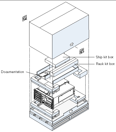
Check that you have received all of the parts you ordered. Peripherals that are not factory installed are shipped separately. Contact Sun Microsystems or your distributor or reseller if you are missing anything.
You need one 4-post rackmounting kit for each Sun Fire V490 server you intend to install into a cabinet. You also need this document and the Rack Alignment template from the ship kit.
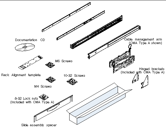
The plastic bags of hardware contain screws shown below in actual size.

Any screws not used for rackmounting are spares.
|
Note - Bar nuts are required (but not included) for non-threaded cabinets. See the instructions provided with your cabinet for more information. |
You will need the following tools when rackmounting the server:
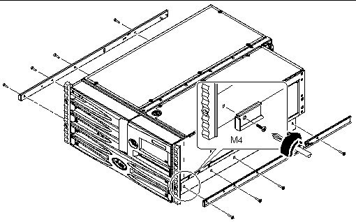
 Attach the inner glides to the chassis using four M4 screws for each inner glide.
Position the straight end of the inner glide toward the front of the system. Align the first hole on the inner glide with the first hole on the chassis.
1. Open, and remove if applicable, the front and back doors of the cabinet.
See the instructions provided with your cabinet.
2. Stabilize the cabinet by extending its anti-tip legs or bolting the cabinet securely to the floor.
See the instructions provided with your cabinet and read 4-Post Cabinet Requirements.
3. Remove the side panels from the cabinet, if applicable.
See the instructions provided with your cabinet. Removing the side panels can improve access to the nuts and screws that you install when securing the server in the cabinet.
 Locate and mark the rack rail holes that you will use to attach each slide assembly.
You can either count the holes on the vertical rack rails or use the Rack Alignment template included with your documentation set. Make sure that each slide assembly is installed at the same height front-to-back and side-to-side in the rack.
The Rack Alignment template is five rack units (8.75 in/22.22 cm) tall. Because the holes on a standard rack rail are arranged in sets of three holes spaced 5/8ths, 5/8ths, and 1/2 of an inch apart, which two holes you use for attaching a slide assembly varies depending on exactly where in the rack the server is located.
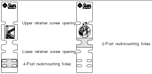
One side of the Rack Alignment template is for 2-post rackmounting, the other side is for 4-post rackmounting. For 2-post rackmounting instructions, see Chapter 2.
The 4-post mounting holes on the Rack Alignment template are for mounting the slide bracket to the vertical rack rail. The upper and lower retainer screw openings in the template locate the server retainer screws that hold the server in the rack after it is installed.
The following figure shows both sides of the Rack Alignment template.
To use the Rack Alignment template, complete these steps:
a. Place the Rack Alignment template over the left front vertical rack rail, then move the bottom of the template to the location on the rack rail where the bottom of the server will be located.
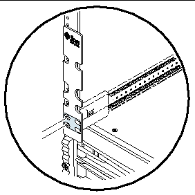
b. Adjust the Rack Alignment template until the lower retainer screw opening is centered on a hole in the rail.
c. Looking through the two slide bracket mounting holes on the Rack Alignment template, locate and mark the two holes on the vertical rack rail that are most visible through the template.
Use these two mounting holes to attach the slide assembly to the front rail. Mark the corresponding holes on the right front vertical rack rail.

|
Caution - Stabilize the cabinet by extending its anti-tip legs or bolting the cabinet securely to the floor. |
1. Use the Rack Alignment template to locate and mark mounting holes on the vertical rack rails.
See How to Locate the Mounting Holes.
2. Adjust the back mounting brackets to accommodate the depth of the rack.
a. Loosen the three 8-32 lock nuts that secure the back mounting bracket to the slide assembly.
b. Position a slide assembly in the cabinet where you marked the mounting holes.
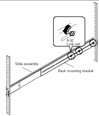
c. Move the bracket forward or backward on the slide assembly until you have the correct position to accommodate the depth of the rack.
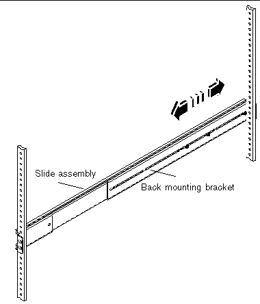
d. Loosely tighten the three lock nuts that secure the back mounting bracket to the slide assembly. Do not fully tighten the lock nuts.
e. Repeat these steps to adjust the other back mounting bracket.
3. With the help of an assistant, position the slide assembly on the right mounting rail as viewed from the front.
The front (short) mounting bracket should be at the front of the rack.
a. Use the holes you marked in Step 1.
b. Use the same slide assembly you adjusted in Step 2.
c. Make sure that the slide assembly is level front-to-back.
4. Using the appropriate screws for the rack, attach the front mounting bracket to the front rail of the rack and attach the back (long) mounting bracket of the same slide assembly to the back rail of the rack.
a. Count the rack rail holes to ensure that you are matching the holes used on the front rail.
b. Use the appropriate screws for your type of rack:
Partially tighten the front bracket screws and the back bracket screws.
|
Note - Do not fully tighten the screws that attach the brackets to the vertical mounting rails until after you use the slide assembly spacer to make sure that the rails are evenly spaced and aligned. |
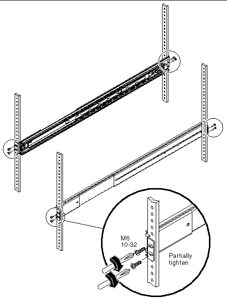
5. Repeat Steps 3 and 4 for the other slide assembly.
6. Use the slide assembly spacer to make sure that the slide assemblies are evenly spaced and aligned correctly.
The slide assembly spacer is included in the rack kit.
a. Place the slide assembly spacer over the left and right slide assemblies at the front of the rack.
The slots on the slide assembly spacer should fit evenly over the rails.
b. With the slide assembly spacer in place, fully tighten the front bracket screws.
c. Place the slide assembly spacer over the left and right slide assemblies at the back of the rack.
d. With the slide assembly spacer in place, fully tighten the back bracket screws.
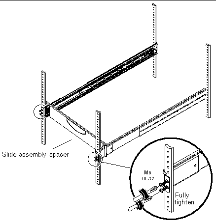
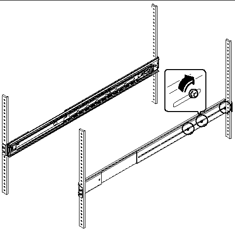
7. Make sure that each slide assembly is fully retracted into the cabinet as shown in the next figure.
8. Fully tighten the three 8-32 lock nuts on the back mounting bracket.

|
Caution - The server is heavy. Two persons are required to install or remove the server into the rack. |
|
Note - Make sure that each slide assembly is fully retracted into the cabinet and check that the ball-bearing runner on each slide assembly is all the way forward. |
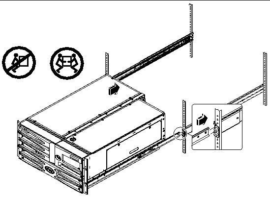
1. Lift the server (one person on each side of the server) and approach the cabinet with the back of the server facing the front of the cabinet.
2. Align the rounded ends of the inner glides on the server with the slide assemblies in the cabinet.
|
Note - Make sure that the inner glides attached to the server are inserted within the ball-bearing runners, and the server is level when inserting it into the ball-bearing runners. |
3. Holding the server level, slide it evenly all the way into the cabinet.
|
Note - Make sure that the server is level when inserting it into the ball-bearing runners. |
|
Tip - Slide the server in and out of the cabinet slowly and carefully to ensure that the slide assemblies are working correctly and are free from obstructions. |
|
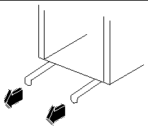
Note - If you fully extend the server out of the cabinet, press the catch on each inner glide to slide the server all the way back into the cabinet. |
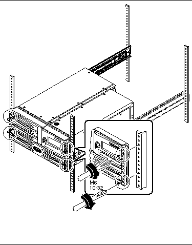
4. Secure the server to the front vertical mounting rails using either four M6 screws or four 10-32 screws included in the rack kit.
Copyright © 2005, Sun Microsystems, Inc. All Rights Reserved.