| C H A P T E R 4 |
|
Components Descriptions |
Components within the Netra CT servers can be broken down into three categories:
In addition, some components are available only for the Netra CT 810 server, some are available only for the Netra CT 410 server, and some are available for both types of servers.
Finally, components can be further broken down into either hot-swappable or cold-swappable components:
Refer to TABLE 4-1 for a list of components available for the different models of the Netra CT server. All information applies to both the Netra CT 810 server and the Netra CT 410 server unless otherwise noted.
|
A hot-swappable component. Refer to Air Filters. |
A hot-swappable component. Refer to Air Filters. |
|
|
A hot-swappable component. Refer to Alarm Card. |
A hot-swappable component. Must be installed along with alarm rear transition card. Refer to Alarm Card and Alarm Rear Transition Card. |
|
|
A hot-swappable component. Must be installed along with alarm card. Refer to Alarm Card and Alarm Rear Transition Card. |
||
|
A hot-swappable component. Refer to Fan Tray and Fans. |
A hot-swappable component. Refer to Fan Tray and Fans. |
|
|
A hot-swappable component. Refer to Hard Disk Drive. |
A hot-swappable component. Refer to Hard Disk Drive. |
|
|
A hot-swappable component. Must be installed along with a host CPU front transition card. Refer to Host CPU Card and Host CPU Front Transition Card.[1] |
A hot-swappable component. Must be installed along with a host CPU rear transition card. Refer to Host CPU Card and Host CPU Rear Transition Card.1 |
|
|
||
|
A hot-swappable component. Must be installed along with a host CPU card. Refer to Host CPU Card and Host CPU Front Transition Card.1 |
||
|
A hot-swappable component. Must be installed along with a host CPU card. Refer to Host CPU Card and Host CPU Rear Transition Card.1 |
||
|
A hot-swappable component. Refer to Front-Access Model Satellite CPU or I/O Cards. |
Hot-swappable components. Both the front I/O card and the I/O rear transition card must be installed. Refer to Rear-Access Model Satellite CPU or I/O Cards. |
|
|
|
|
|
|
|
|
A hot-swappable component. Refer to Front-Access Model Satellite CPU or I/O Cards. |
Hot-swappable components. Both the front satellite CPU card and the satellite CPU rear transition card must be installed. Refer to Rear-Access Model Satellite CPU or I/O Cards. |
|
|
A hot-swappable component. Both the front satellite CPU card and the satellite CPU rear transition card must be installed. Refer to Rear-Access Model Satellite CPU or I/O Cards. |
||
|
A hot-swappable component. Refer to System Controller Board. |
A hot-swappable component. Refer to System Controller Board. |
|
|
A hot-swappable component. Refer to System Status Panel. |
A hot-swappable component. Refer to System Status Panel. |
Following are components that are available for both front and rear-access model servers:
|
Note - This section gives general information about the host CPU in the Netra CT server. For more specific information about the Netra CP2140 host CPU card, refer to the Netra CP2140 Technical Reference and Installation Manual (816-4908-xx) and the Netra CP2140 CompactPCI Board Product Note (816-4870-xx). In addition, there are restrictions for the Netra CP2140 host CPU card that are specific to the Netra CT server; refer to Restrictions for the Netra CT Server for more information. |
Every Netra CT server contains one host CPU card. The Netra CT 810 servers and the Netra CT 410 servers use the same host CPU card. A specific slot is reserved for the host CPU card in both the Netra CT 810 server (slot 1) and the Netra CT 410 server (slot 3), indicated by a red card cage guide. FIGURE 4-1 shows where the host CPU card must be installed in both types of servers.
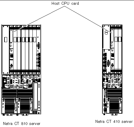
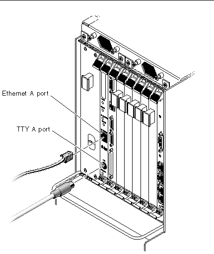
FIGURE 4-2 shows the ports on a host CPU card. The TTY A port is available on the host CPU card for the front-access model of the Netra CT 410 server because the CPU front transition card for the Netra CT 410 server does not have a TTY A port (see Host CPU Front Transition Card for more information on the CPU front transition card for the Netra CT 410 server). Do not use the TTY A port on the host CPU card for the rear-access models of the Netra CT 810 server or Netra CT 410 server because the CPU transition cards for those models all have a TTY A port.
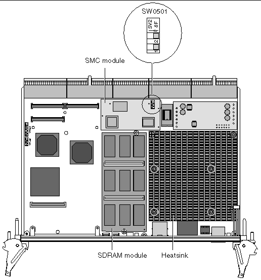
The documentation that comes with the Netra CP2140 host CPU card explains how to set the SMC module settings on the SW0501 switches when installing a Netra CP2140 host CPU card into high availability chassis or a non-high availability chassis. The Netra CT server supports high availability hot swap; however, because the alarm card controls the high availability on the Netra CT server, the settings on the SW0501 switches should actually be set in the default, non-high availability settings.
Following are the correct (default) settings for the SMC module switch SW0501 for the Netra CT server (see FIGURE 4-3 and FIGURE 4-4):

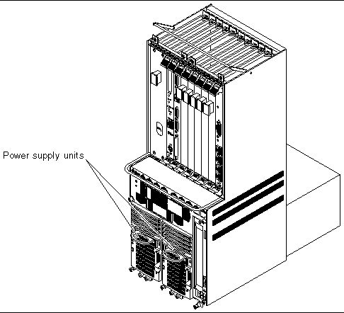
Every Netra CT 810 server contains two power supply units, and every Netra CT 410 server contains one power supply unit. The Netra CT 810 servers and Netra CT 410 servers use the same power supply units.
For the Netra CT 810 server, one power supply unit is redundant of the other. Feeds are supplied to each of the power supply units through the DC power distribution units or AC power entry unit (see Chapter 2 for more information). Because each Netra CT 810 server has two power supply units, the server receives power from two power sources. If one power source or one power supply unit fails, the server will continue normal operation using the remaining power supply. Note that this is not the case for the Netra CT 410 server because it has only one power supply unit.
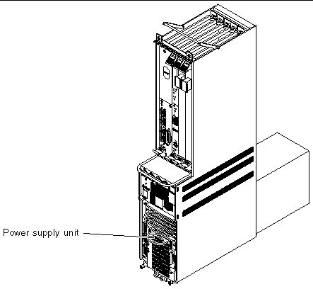
The locations of the power supply units in the Netra CT 810 server are illustrated in FIGURE 4-5 and the location of the power supply unit in the Netra CT 410 server is illustrated in FIGURE 4-6.
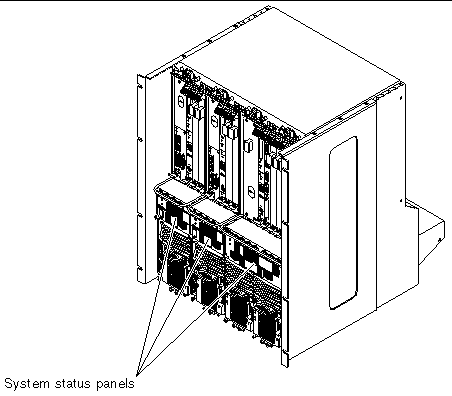
The system status panel is a module designed to give feedback on the status of the key components within the Netra CT servers. The location of the system status panel in the Netra CT 810 servers and Netra CT 410 servers is illustrated in FIGURE 4-7.
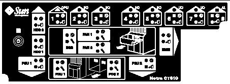
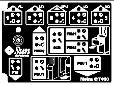
The system status panel has one set of LEDs for each component within that particular server. FIGURE 4-8 shows the LEDs on the system status panel for the Netra CT 810 server, and FIGURE 4-9 shows the LEDs on the system status panel for the Netra CT 410 server.
|
I/O cards or satellite CPU cards (●) installed in slot 4 and 5 |
||
|
Host CPU front transition card or host CPU front termination board |
||
Each major component in the Netra CT 810 server or Netra CT 410 server has a set of LEDs on the system status panel that gives the status on that particular component. Each component will have either the green Power and the amber Okay to Remove LEDs (FIGURE 4-10) or the green Power and amber Fault LEDs (FIGURE 4-11). Note that the components in the Netra CT servers all have the green Power LED, and they will have either the amber Okay to Remove LED or the amber Fault LED, but not both.


There is also a green system power LED and power on/off button located on the system status panel. When the system is off, the system power LED will be unlit. Pressing the system power button when the system is off will start the power-up sequence. Once the system is completely powered up, the system power LED remains on.
When the system is powered on, pressing the system power button for less than 4 seconds will start the orderly power-down sequence--in a manner that no persistent operating system data structures are corrupted--indicated by a blinking LED. In the orderly power-down, applications in service may be abnormally terminated and no further services will be invoked by the CPU. Once the CPU has reached a quiescent state (run level-0, as if init 0 had been invoked), then the power suppl(ies) will turn off, indicated by the LED changing from a blinking state to the off state.
If the button is held down for 4 seconds or longer, the power suppl(ies) are turned off without any intervention of the CPU; that is, the "emergency" power-down sequence occurs.
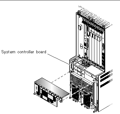
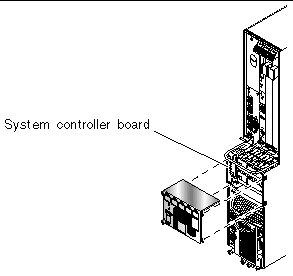
The system controller board is a hot-swappable component located behind the system status panel; you must remove the system status panel to access the system controller board. The system controller board feeds system status information to the system status panel, where LEDs give feedback on the status of the key components within the Netra CT servers.
The location of the system controller board in the Netra CT 810 server is illustrated in FIGURE 4-12 and the location of the system controller board in the Netra CT 410 server is illustrated in FIGURE 4-13.
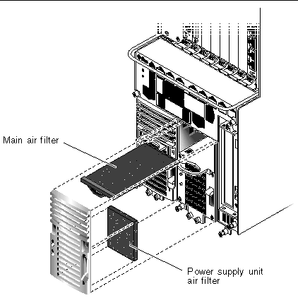
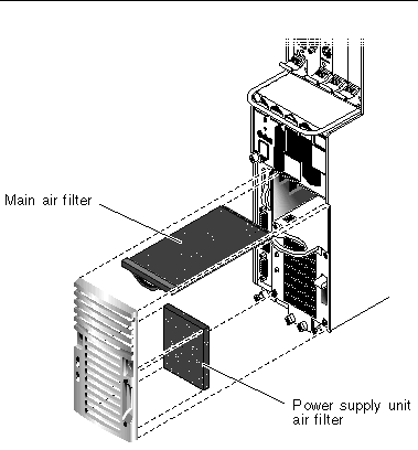
Both the Netra CT 810 servers and the Netra CT 410 servers have two types of air filters: a power supply unit air filter, which filters the air going into the power supply, and a main air filter, which filters the air going into the server. Both air filters are located in the power supply unit. The power supply unit air filter is located at the front of the power supply unit and the main air filter is located in a tray at the top of the power supply unit. Both sets of air filters should be replaced every three to six months. If your server environment is especially dirty, you may have to replace them more frequently. The power supply unit air filter must be in place for safe operation. FIGURE 4-14 shows the locations of the air filters in a Netra CT 810 server power supply unit, and FIGURE 4-15 shows the locations of the air filters in a Netra CT 410 server power supply unit.
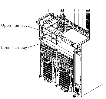
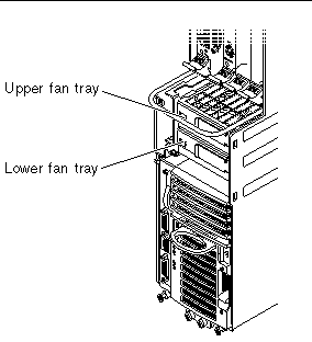
Both the Netra CT 810 servers and the Netra CT 410 servers have two fan trays. The fan tray for the Netra CT 810 server has a single large fan in each tray, while the fan tray for the Netra CT 410 server has two smaller fans in each tray. The fan tray is designed to be hot-swappable.
If the temperature rises above 158°F (70°C), the CPU card sends out a warning that the system is overheating. If the temperature rises above 167°F (75°C), then the system shuts down automatically. Note that the temperatures above are not ambient air temperatures, but rather the CPU temperatures that are monitored by a thermistor located under the heatsink on the host CPU card.
If one fan tray fails, you must replace the failed fan tray as soon as possible. Even though the system can run on one fan tray, if the temperature rises, a single fan tray may not be able to cool the system properly.
The fans are located underneath the card cage behind the system status panel (see System Status Panel for the location of the system status panel). They are recessed into the operations card cage to maximize the air flow across the CompactPCI cards. FIGURE 4-16 shows the locations of the fan trays in a Netra CT 810 server and FIGURE 4-17 shows the locations of the fan trays in a Netra CT 410 server. Note that the system status panel has been removed in both figures.
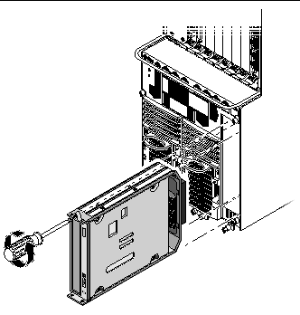
Hard disk drives are fully hot-swappable. Each hard disk drive has its own latching mechanism to ensure a positive lock with the chassis. You can have a maximum of two hard disk drives in the Netra CT 810 server and one hard disk drive in the Netra CT 410 server. The Netra CT 810 servers and the Netra CT 410 servers both use the same hard disk drives.
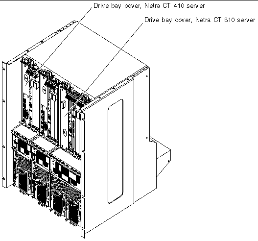
A specific slot is reserved for the hard disk drives in both the Netra CT 810 servers and the Netra CT 410 servers. The hard disk drives will be behind the drive bay cover on your system. There would be a maximum of two hard disk drives behind the drive bay cover in a Netra CT 810 server and one behind the drive bay cover in a Netra CT 410 server.
Following are the SCSI IDs for the hard disk drives:
In addition, there are two separate SCSI chains in the Netra CT 810 server for the SCSI devices:
The removeable media module consists of either a DVD or a 4-mm digital audio tape (DAT) drive, either of which is placed into the system from the front. The removeable media module is available only for the Netra CT 810 server.
Following are the SCSI IDs for the devices used in the removeable media module:
In addition, there are two separate SCSI chains in the Netra CT 810 server for the SCSI devices. The removeable media device and the upper hard disk drive (HDD 0) are both on the first SCSI chain; the lower hard disk drive (HDD 1) is alone on the second SCSI chain.
The alarm card is a standard component for both the Netra CT 410 servers and Netra CT 810 servers. There are two different types of alarm cards used in the two servers:
Significant Reliability, Availability, Serviceability (RAS) functions are provided by the alarm card. The alarm card has its own CPU, a Motorola MPC850 processor, plus its own real-time operating system and application software.
The alarm card and its accompanying software perform the following functions on the Netra CT server:
The alarm card has the following remote interfaces:
A specific slot is reserved for the alarm card in both the Netra CT 810 server and the Netra CT 410 server. FIGURE 4-20 shows the single-wide 6U alarm card used in the Netra CT 810 server and the diskless Netra CT 410 server. FIGURE 4-21 shows the double-wide 3U alarm card used in the diskfull Netra CT 410 server.
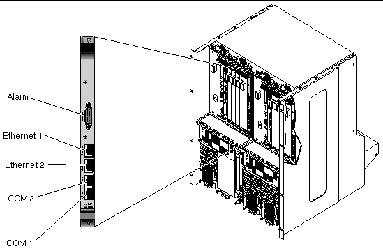
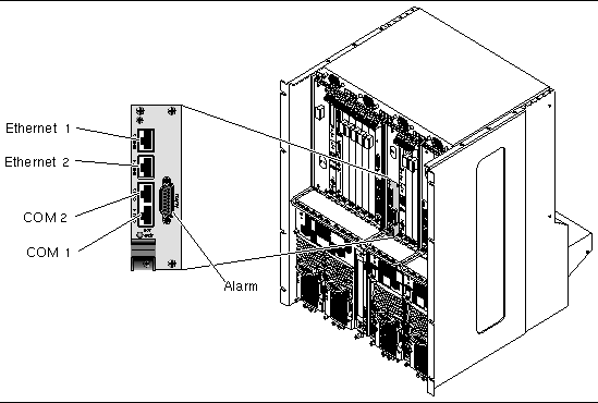
There is also an alarm rear transition card available for the rear-access models of the Netra CT 810 server and Netra CT 410 server. Either the single-wide 6U alarm card or the double-wide 3U alarm card can be used in conjunction with the alarm rear transition card. The alarm rear transition card must be installed in the same slot, at the rear of the server, as the alarm card. Refer to Alarm Rear Transition Card for more information.
Following are components that are available only for front-access model servers:
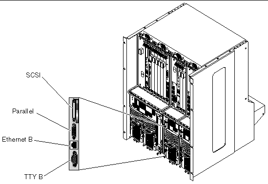
The host CPU front transition card is required to provide connections from the host CPU card to standard I/O connectors on the front. The host CPU front transition card for the Netra CT 410 server is 3U and is installed in the slot next to the power supply.
FIGURE 4-22 shows the location of the host CPU front transition card in a Netra CT 410 server. Note that the host CPU front transition card for the Netra CT 410 server does not have a TTY A port, so you must use the COM port on the host CPU card as the TTY A port for the front-access model of the Netra CT 410 server (see Host CPU Card for more information on the COM port on the host CPU card).
Visit the www.sun.com site for more information on satellite CPU and I/O cards that are supported on the Netra CT server.
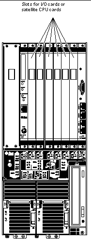
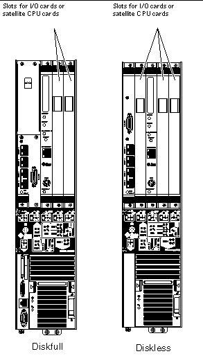
Card slots designated for satellite CPU, I/O cards and alarm cards have black rails; card slots with red rails are reserved for the host CPU card. There are also labels at the front of the servers and the rear of the chassis that show the I/O slot numbers for front-access and rear-access models, as well as the cards that are supported in each slot. For front-access models, you can also determine the I/O slot numbers for your servers by using the I/O slot numbers shown on the system status panels. A satellite CPU or I/O card cannot be installed in the slots meant for the host CPU card or alarm card. All the slots for satellite CPU or I/O cards in the Netra CT server support hot swap.
The following figures show the slots available for satellite CPU or I/O cards in the Netra CT servers:
Following are components that are available only for rear-access model servers:
The host CPU rear transition card is required to provide connections from the host CPU card to standard I/O connectors on the rear. In addition, the host CPU rear transition card provides two MIIs to two 10/100 twisted-pair Ethernet connections. The host CPU card must be installed in the front of the server in order for the host CPU rear transition card to work (refer to Rear-Access Models for more information). The same host CPU rear transition card is used by both the Netra CT 810 server and the Netra CT 410 server.
Use only the Netra CT-supported host CPU rear transition card in the Netra CT server; do not use the XCP2040-TRN I/O transition card that is available with the Netra CP2140 board. Refer to FIGURE 4-25 to determine if the host CPU rear transition card you have is supported or unsupported on a Netra CT server.
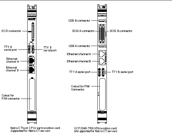
FIGURE 4-26 shows the location of the host CPU rear transition card on the Netra CT 810 server, and FIGURE 4-27 shows the location of the host CPU rear transition card on the Netra CT 410 server.
The host CPU front termination board is installed in the slot that would normally be occupied by the host CPU front transition card in a front-access model of the Netra CT 410 server. The host CPU front termination board terminates the SCSI chain for the rear-access Netra CT 410 server.
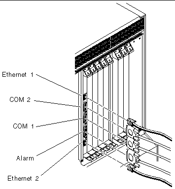
The alarm rear transition card extends the ports on the alarm card installed at the front of the server to the alarm rear transition card installed at the rear of the server. The same alarm rear transition card is used by both the Netra CT 810 server or the Netra CT 410 server. The alarm card must be installed in the front of the server in order for the alarm rear transition card to work (refer to Rear-Access Models for more information). Ethernet port 1 is a 10Mbps Ethernet port, and Ethernet port 2 is a 10/100 Mbps Ethernet port. FIGURE 4-28 shows the ports for the alarm rear transition card. FIGURE 4-29 shows the location of the alarm rear transition card in a Netra CT 810 server, and FIGURE 4-30 shows the location of the alarm rear transition card in a Netra CT 410 server.
The satellite CPU rear transition card set consists of two separate cards:
The satellite CPU card is installed from the front of the Netra CT server; however, no cables are connected to the satellite CPU card. It is the same satellite CPU card that is used in the front-access model of the Netra CT server.
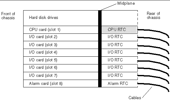
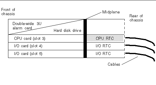
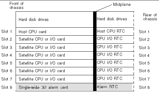
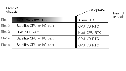
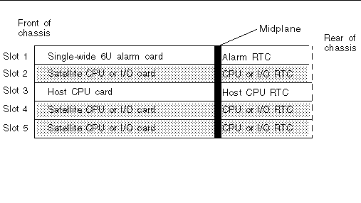
The rear transition card extends the ports from the PMCs installed in the satellite CPU card to the PIMs installed in the satellite CPU rear transition card. The satellite CPU card must be installed in the same slot at the front of the server in order for the satellite CPU rear transition card to work. For example, if you install a satellite CPU rear transition card in I/O slot 3 at the rear of a Netra CT 810 server, you must also install the accompanying satellite CPU card in I/O slot 3 at the front of the server.
FIGURE 4-31 and FIGURE 4-32 give graphical representations of how the satellite CPU cards should align with the satellite CPU rear transition cards (RTCs). Note that, if you are facing the front of the server, the I/O slots read from left to right, whereas they read from right to left if you are facing the rear of the server.
The I/O rear transition card set consists of two separate cards:
The front I/O card contains the ASICs for the associated I/O card and is installed from the front of the server; however, no cables are connected to the front I/O card.
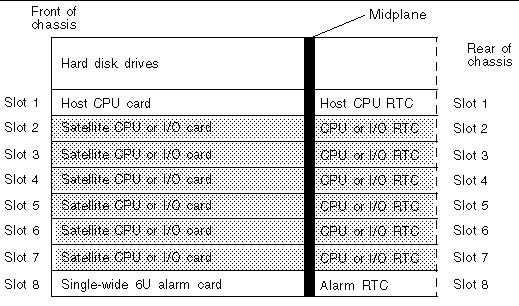
The I/O rear transition card extends the ports for a particular I/O card to the rear of the server. The I/O rear transition card and the front I/O card must be installed in the same slot at the front of the server in order for the I/O rear transition card to work. For example, if you install an I/O rear transition card in I/O slot 3 at the rear of a Netra CT 810 server, you must also install the accompanying front I/O card in I/O slot 3 at the front of the server.
When one of the two cards fails, you should replace both the front I/O card and the I/O rear transition card. FIGURE 4-31 and FIGURE 4-32 give graphical representations of how the front I/O cards should align with the I/O rear transition cards (RTCs). Note that, if you are facing the front of the server, the I/O slots read from left to right, whereas they read from right to left if you are facing the rear of the server.
Copyright © 2003, Sun Microsystems, Inc. All rights reserved.