| C H A P T E R 3 |
|
Server Description |
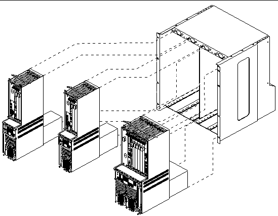
The Netra CT servers slide into the chassis and are secured to the chassis using captive screws at the top and base of the server. Each Netra CT server is an independent computer, with its own host CPU board and rear transition module (RTM), midplane, I/O slots, and, in some cases, storage devices and removable media.
The Netra CT chassis supports two types of Netra CT servers:
|
Note - Also, the Netra CT chassis supports the Netra CT 800 server and the Netra CT 400 server. For information on those servers, refer to the documentation that you received with the servers. |
TABLE 3-1 provides the physical specifications for the Netra CT 810 server, and FIGURE 3-1 shows the Netra CT 810 server.
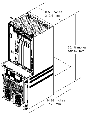
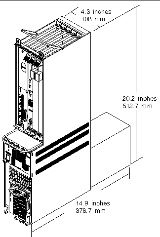
TABLE 3-2 provides the physical specifications for the Netra CT 410 server, and FIGURE 3-2 shows the Netra CT 410 server.
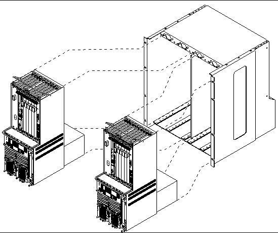
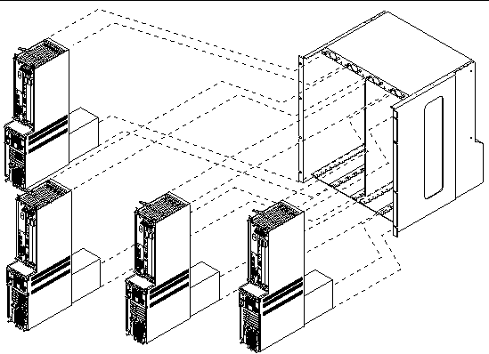
The following combinations of the two server types are supported in a Netra CT chassis:
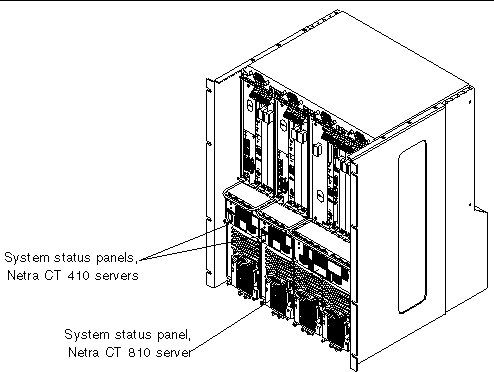
If you are uncertain whether you have a Netra CT 810 server or a Netra CT 410 server in a chassis, locate the system status panel (FIGURE 3-6) on the front of the chassis.
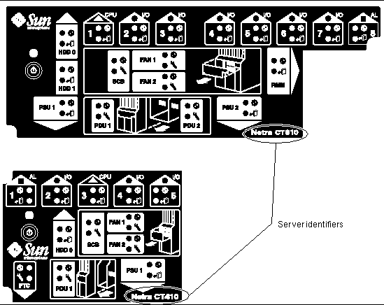
The server identifier at the bottom right corner of the system status panel indicates a Netra CT 810 server or a Netra CT 410 server (FIGURE 3-7).
Each Netra CT server has a midplane. A midplane is the functional equivalent of a backplane. The CPU board, storage devices, and I/O boards all plug into the midplane from the front of the chassis, and the rear transition modules plug into the midplane from the rear. The midplane for each server is secured to the rear of the server unit.
The midplanes support the 5V-V10 CompactPCI bus. Although the CPU board only supports the 32-bit CompactPCI bus, the midplanes in both Netra CT servers allow 64-bit peer-to-peer transactions. Also, the midplanes support the H.110 telephony bus on all but the following slots:
Slot 1 in the Netra CT 810 server and slot 3 in the Netra CT 410 server are reserved for the host CPU board. Slot 8 in the Netra CT 810 server and slot 1 in the Netra CT 410 server are proprietary I/O slots, intended solely for alarm cards. All CompactPCI slots support basic, full, and high-availability hot-swap on every CompactPCI slot.
FIGURE 3-8 shows the different buses on the Netra CT 810 server, and FIGURE 3-9 shows the different buses on the Netra CT 410 server.
Both Netra CT 410 servers and Netra CT 810 servers are rear-access models. A rear-access model is designed so that all the cables to the CompactPCI boards are connected from the rear of the chassis.
For both the Netra CT 810 server and the Netra CT 410 server, all the cables are connected to rear transition modules installed at the rear of the Netra CT server. The rear transition modules, in effect, extend the CompactPCI boards installed in each slot from the midplane to the rear of the chassis.
Each rear transition module installed must have an accompanying board installed in the front board cage of the server; however, the type of board installed in the front board cage varies:
FIGURE 3-10 shows the top view of a Netra CT 810 server with an alarm card installed, and FIGURE 3-11 shows the top view of a Netra CT 410 server.
The slot to the left of the power supply in a Netra CT 410 server is reserved for the host CPU front termination board (see Host CPU Front Termination Boards (FTB) for more information).
Copyright © 2007, Sun Microsystems, Inc. All Rights Reserved.