Sun SNMP Management Agent Addendum for the Netra 440 Server

This document describes how the Netratrademark 440 server fans, power supplies, and LED indicators are represented in the Suntrademark Simple Network Management Protocol (SNMP) Agent for Sun Firetrademark and Netra Systems. This document contains the following sections:


Note - For instructions on installing and using the Sun SNMP Management Agent, refer to the Sun SNMP Management Agent for Sun Fire and Netra Systems (817-2559-xx) manual. See Sun SNMP Management Agent for more information.


Sun SNMP Management Agent

The Sun SNMP Management Agent for Sun Fire and Netra Systems provides the management of supported systems using the Simple Network Management Protocol (SNMP). Using the Sun SNMP Management Agent, you can monitor inventory, configuration, and service indicators, as well as environmental and fault reports.

You can download the Sun SNMP Management Agent for Sun Fire and Netra Systems software and documentation at the following web site:

http://www.sun.com/servers/entry/sun_management.html

For instructions on installing and configuring the software, refer to the Sun SNMP Management Agent for Sun Fire and Netra Systems (817-2559-xx). The SNMP management agent manual contains a detailed overview of the agent software, including an introduction to the SNMP environment and a description of how the agent models hardware platforms using the Sun Platform SNMP model (SunPSM). The manual also describes how the SNMP interface presents managed objects and their relationships using the ENTITY-MIB and SUN-PLATFORM-MIB management information bases (MIB).

This document supplements the Sun SNMP Management Agent for Sun Fire and Netra Systems manual by documenting how the agent represents the Netra 440 server fans, power supplies, and certain LED indicators. This document provides Netra 440 server-specific information only. For complete descriptions of the SNMP agent terminology, management models, and trap properties, refer to the Sun SNMP Management Agent for Sun Fire and Netra Systems manual.

For additional information about the Netra 440 server, refer to the server's documentation at the following web site:

http://www.sun.com/products-n-solutions/hardware/docs/Servers/Netra_Servers/Netra_440/


Netra 440 Server SNMP Containment Model

TABLE 1 presents an example of how the Sun SNMP agent models the Netra 440 server component hierarchy. Because this component hierarchy may vary depending on your server and the SNMP agent software version, query the SNMP agent to identify your server's hierarchy. To locate these server components, see the figures in Component and Indicator Identification.

TABLE 1 Netra 440 Server Containment Model (Hierarchy)

Model Description

For Location, See:

Netra 440 Chassis


Alarm Board


Critical Alarm Relay


Major Alarm Relay


Minor Alarm Relay


User Alarm Relay


System Board


OpenBoot PROM


Battery


Battery Voltage Monitor


CPU/Memory Slot 0 (far left - viewed from front)

FIGURE 4 - item 2


CPU/Memory Module 0

FIGURE 4 - item 2


Processor 0 Memory Bank 0

FIGURE 4 - item 2

FIGURE 5 - item 5


Processor 0 Memory Bank 0 DIMM 0

FIGURE 4 - item 2

FIGURE 5 - item 1


Processor 0 Memory Bank 0 DIMM 1

FIGURE 4 - item 2
FIGURE 5 - item 2


Processor 0 Memory Bank 1

FIGURE 4 - item 2

FIGURE 5 - item 6


Processor 0 Memory Bank 1 DIMM 0

FIGURE 4 - item 2
FIGURE 5 - item 3


Processor 0 Memory Bank 1 DIMM 1

FIGURE 4 - item 2
FIGURE 5 - item 4


CPU 0 (far left - viewed from front)

FIGURE 4 - item 2


CPU 0 Core Temperature Monitor


CPU 0 Power OK Fault Sensor


CPU 0 Ambient Temperature Sensor


CPU/Memory Slot 1 (2nd from left - viewed from front)

FIGURE 4 - item 3


CPU/Memory Module 1

FIGURE 4 - item 3


Processor 1 Memory Bank 0

FIGURE 4 - item 3

FIGURE 5 - item 5


Processor 1 Memory Bank 0 DIMM 0

FIGURE 4 - item 3

FIGURE 5 - item 1


Processor 1 Memory Bank 0 DIMM 1

FIGURE 4 - item 3

FIGURE 5 - item 2


Processor 1 Memory Bank 1

FIGURE 4 - item 3

FIGURE 5 - item 6


Processor 1 Memory Bank 1 DIMM 0

FIGURE 4 - item 3

FIGURE 5 - item 3


Processor 1 Memory Bank 1 DIMM 1

FIGURE 4 - item 3

FIGURE 5 - item 4


CPU 1 (2nd from left - viewed from front)

FIGURE 4 - item 3


CPU 1 Core Temperature Monitor


CPU 1 Power OK Fault Sensor


CPU 1 Ambient Temperature Sensor


CPU/Memory Slot 2 (2nd from right - viewed from front)

FIGURE 4 - item 4


CPU/Memory Module 2

FIGURE 4 - item 4


Processor 2 Memory Bank 0

FIGURE 4 - item 4

FIGURE 5 - item 5


Processor 2 Memory Bank 0 DIMM 0

FIGURE 4 - item 4

FIGURE 5 - item 1


Processor 2 Memory Bank 0 DIMM 1

FIGURE 4 - item 4

FIGURE 5 - item 2


Processor 2 Memory Bank 1

FIGURE 4 - item 4

FIGURE 5 - item 6


Processor 2 Memory Bank 1 DIMM 0

FIGURE 4 - item 4

FIGURE 5 - item 3


Processor 2 Memory Bank 1 DIMM 1

FIGURE 4 - item 4

FIGURE 5 - item 4


CPU 2 (2nd from right - viewed from front)

FIGURE 4 - item 4


CPU 2 Core Temperature Monitor


CPU 2 Power OK Fault Sensor


CPU 2 Ambient Temperature Sensor


CPU/Memory Slot 3 (far right - viewed from front)

FIGURE 4 - item 5


CPU/Memory Module 3

FIGURE 4 - item 5


Processor 3 Memory Bank 0

FIGURE 4 - item 5

FIGURE 5 - item 5


Processor 3 Memory Bank 0 DIMM 0

FIGURE 4 - item 5

FIGURE 5 - item 1


Processor 3 Memory Bank 0 DIMM 1

FIGURE 4 - item 5

FIGURE 5 - item 2


Processor 3 Memory Bank 1

FIGURE 4 - item 5

FIGURE 5 - item 6


Processor 3 Memory Bank 1 DIMM 0

FIGURE 4 - item 5

FIGURE 5 - item 3


Processor 3 Memory Bank 1 DIMM 1

FIGURE 4 - item 5

FIGURE 5 - item 4


CPU 3 (far right - viewed from front)

FIGURE 4 - item 5


CPU 3 Core Temperature Monitor


CPU 3 Power OK Fault Sensor


CPU 3 Ambient Temperature Sensor


PCI Slot 0 (33Mhz 5V) (far left - viewed from front)

FIGURE 3 - item 11


PCI Slot 1 (33Mhz 5V) (2nd from left - viewed from front)[1]

FIGURE 3 - item 10


PCI Slot 2 (33/66Mhz 3.3V) (3rd from left - viewed from front)*

FIGURE 3 - item 9


PCI Slot 3 (33Mhz 5V) (3rd from right - viewed from front)*

FIGURE 3 - item 8


PCI Slot 4 (33/66Mhz 3.3V) (2nd from right - viewed from front)*

FIGURE 3 - item 7


PCI Slot 5 (33/66Mhz 3.3V) (far right - viewed from front)

FIGURE 3 - item 6


System Controller Slot


System Controller


Motherboard Ambient Temperature Sensor


+1.5V Rail Monitor


+3.3V Rail Monitor


Standby Monitor


+5V Rail Monitor


+12V Rail Monitor


-12V Rail Monitor


Ethernet 0 1.2V Analog Rail Monitor


Ethernet 0 1.2V Digital Rail Monitor


Ethernet 1 1.2V Analog Rail Monitor


Ethernet 1 1.2V Digital Rail Monitor


SCSI Controller 1.8V Rail Monitor


Tomatillo/Cassini 2.5V Rail Monitor


Motherboard Power OK Fault Sensor


Internal SCSI Termination Power Rail Fault Sensor


External SCSI Termination Power Rail Fault Sensor


SCSI Disk Backplane

FIGURE 4 - item 6


Chassis Indicator Panel


System Active Indicator (front)

FIGURE 1 - item 3


System Locator (front)

FIGURE 1 - item 1


System Service-Required Indicator (front)

FIGURE 1 - item 2


Asynchronous Serial Port

FIGURE 3 - item 24


SCSI Port

FIGURE 3 - item 17


Alarm Port

FIGURE 3 - item 25


USB 0 Port (top left - viewed from rear)

FIGURE 3 - item 22


USB 1 Port (bottom left - viewed from rear)

FIGURE 3 - item 22


USB 2 Port (top right - viewed from rear)

FIGURE 3 - item 21


USB 3 Port (bottom right - viewed from rear)

FIGURE 3 - item 21


Management Network Port

FIGURE 3 - item 4


Management Serial Port

FIGURE 3 - item 5


Fan Tray 0

FIGURE 2 - item 2


Fan 0

FIGURE 2 - item 2


Fan 0 Active Indicator

FIGURE 2 - item 6


Fan 0 Service-Required Indicator

FIGURE 2 - item 5


Fan 0 Tachometer


Fan Tray 1

FIGURE 2 - item 14


Fan 1

FIGURE 2 - item 14


Fan 1 Active Indicator

FIGURE 2 - item 9


Fan 1 Service-Required Indicator

FIGURE 2 - item 8


Fan 1 Tachometer


Fan Tray 2

FIGURE 2 - item 16


Fan 2

FIGURE 2 - item 16


Fan 2 Active Indicator

FIGURE 2 - item 12


Fan 2 Service-Required Indicator

FIGURE 2 - item 11


Fan 2 Tachometer


Fan Tray 3

FIGURE 4 - item 1


Fan 3

FIGURE 4 - item 1


System Control Keyswitch

FIGURE 1 - item 5


System Active Indicator (rear)

FIGURE 3 - item 3


System Locator (rear)

FIGURE 3 - item 1


System Service-Required Indicator (rear)

FIGURE 3 - item 2


Critical Alarm Indicator (front)

FIGURE 1 - item 8


Major Alarm Indicator (front)

FIGURE 1 - item 9


Minor Alarm Indicator (front)

FIGURE 1 - item 10


User Alarm Indicator (front)

FIGURE 1 - item 11


Hard Disk Drive 0 Bay (left - viewed from front)

FIGURE 2 - item 1


HDD0 Okay To Remove Indicator

FIGURE 2 - item 4


HDD0 Service Required Indicator[2]


Hard Disk Drive 0 (left - viewed from front)

FIGURE 2 - item 1


Hard Disk Drive 1 Bay (2nd from left - viewed from front)

FIGURE 2 - item 3


HDD1 Okay To Remove Indicator

FIGURE 2 - item 7


HDD1 Service Required Indicator|


Hard Disk Drive 1 (2nd from left - viewed from front)

FIGURE 2 - item 3


Hard Disk Drive 2 Bay (2nd from right - viewed from front)

FIGURE 2 - item 15


HDD2 Okay To Remove Indicator

FIGURE 2 - item 10


HDD2 Service Required Indicator|


Hard Disk Drive 2 (2nd from right - viewed from front)

FIGURE 2 - item 15


Hard Disk Drive 3 Bay (right - viewed from front)

FIGURE 2 - item 17


HDD3 Okay To Remove Indicator

FIGURE 2 - item 13


HDD3 Service Required Indicator|


Hard Disk Drive 3 (right1 - viewed from front)

FIGURE 2 - item 17


Power Supply 0 Bay (right - viewed from rear)

FIGURE 3 - item 15


Power Supply 0

FIGURE 3 - item 15


PS 0 Okay-To-Remove Indicator

FIGURE 3 - item 15 and item 14


PS 0 Active Indicator

FIGURE 3 - item 15 and item 12


PS 0 Service-Required Indicator

FIGURE 3 - item 15 and item 13


PS 0 Over-Current Fault Monitor


PS 0 Fan Under-Speed Fault Monitor


PS 0 Over-Voltage Fault Monitor


PS 0 Under-Voltage Fault Monitor


PS 0 Power Inlet Presence Monitor


PS 0 Over-Temperature Fault Monitor


Power Supply 1 Bay (2nd from right - viewed from rear)

FIGURE 3 - item 16


Power Supply 1

FIGURE 3 - item 16


PS 1 Okay-To-Remove Indicator

FIGURE 3 - item 16 and item 14


PS 1 Active Indicator

FIGURE 3 - item 16 and item 12


PS 1 Service-Required Indicator

FIGURE 3 - item 16 and item 13


PS 1 Over-Current Fault Monitor


PS 1 Fan Under-Speed Fault Monitor


PS 1 Over-Voltage Fault Monitor


PS 1 Under-Voltage Fault Monitor


PS 1 Power Inlet Presence Monitor


PS 1 Over-Temperature Fault Monitor


Power Supply 2 Bay (2nd from left - viewed from rear)

FIGURE 3 - item 20


Power Supply 2

FIGURE 3 - item 20


PS 2 Okay-To-Remove Indicator

FIGURE 3 - item 20 and item 14


PS 2 Active Indicator

FIGURE 3 - item 20 and item 12


PS 2 Service-Required Indicator

FIGURE 3 - item 20 and item 13


PS 2 Over-Current Fault Monitor


PS 2 Fan Under-Speed Fault Monitor


PS 2 Over-Voltage Fault Monitor


PS 2 Under-Voltage Fault Monitor


PS 2 Power Inlet Presence Monitor


PS 2 Over-Temperature Fault Monitor


Power Supply 3 Bay (left - viewed from rear)

FIGURE 3 - item 23


Power Supply 3

FIGURE 3 - item 23


PS 3 Okay-To-Remove Indicator

FIGURE 3 - item 23 and item 14


PS 3 Active Indicator

FIGURE 3 - item 23 and item 12


PS 3 Service-Required Indicator

FIGURE 3 - item 23 and item 13


PS 3 Over-Current Fault Monitor


PS 3 Fan Under-Speed Fault Monitor


PS 3 Over-Voltage Fault Monitor


PS 3 Under-Voltage Fault Monitor


PS 3 Power Inlet Presence Monitor


PS 3 Over-Temperature Fault Monitor


System Configuration Card Reader

FIGURE 1 - item 4


System Configuration Card

FIGURE 1 - item 4


DVD Drive Bay

FIGURE 1 - item 6


DVD Drive

FIGURE 1 - item 6


Power Distribution Module Bay

FIGURE 1 - item 7


Power Distribution Module

FIGURE 1 - item 7


Ethernet Port 0 (left - viewed from rear)

FIGURE 3 - item 19


Ethernet Port 1 (right - viewed from rear)

FIGURE 3 - item 18


Component and Indicator Identification

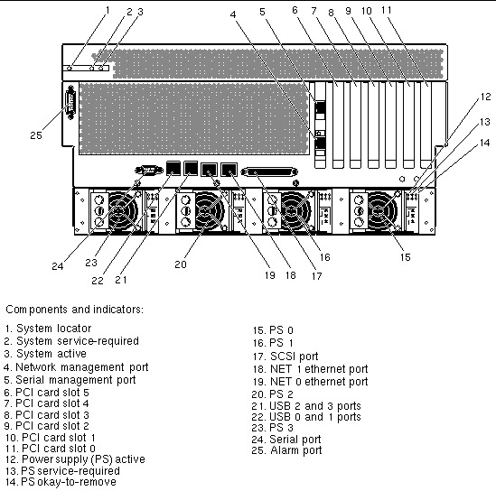
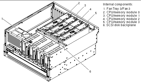
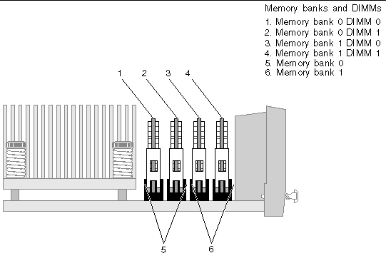
The following figures show the location of the Netra 440 server components. TABLE 1 lists of how the agent models these components in an SNMP hierarchy.
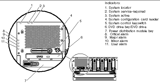
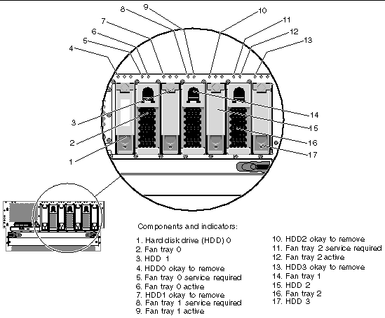
  FIGURE 1 Front Panel Indicators and Components

Figure showing the location of the front panel indicators.

  FIGURE 2 Hard Disk Drive and Fan Tray Components and Indicators

Figure showing the location of the front panel components and hard drive indicators.

  FIGURE 3 Rear Panel Components and Indicators

Figure showing the location of the rear panel components and indicators.

  FIGURE 4 Internal Components

Figure showing the location of the motherboard components.

  FIGURE 5 Memory Banks and DIMMs

Figure showing the location of the memory banks and DIMMs.


Fans and Fan Trays

The Netra 440 server fans in the fan trays are identified in the ENTITY-MIB::entPhysicalTable by the entPhysicalDescr of Fan number, where number is a number in the range from 0 to 3. The fans are represented in the following tables that extend the entPhysicalTable:


Note - The fans in fan trays 0-2 have certain sensors that give status and failure information, whereas the fan in fan tray 3 does not; therefore, the information in the remainder of this section will apply only to the fans in fan trays 0-2, not the fan in fan tray 3. Also, if the fan in fan tray 3 fails, the Netra 440 server automatically shuts down and no SNMP traps are generated.


The fans in fan trays 0-2 contain a tachometer used to indicate the current speed of the fan expressed in revolutions per minute (RPM). The tachometers are identified by their entPhysicalDescr of Fan number Tachometer, where number is a number in the range from 0 to 2 corresponding to the fan tray being monitored. The fan tachometers are represented in the following tables that extend the entPhysicalTable:

Fan Failures

If the speed of a fan falls below the threshold indicated by its tachometer's sunPlatNumericSensorLowerThresholdNonCritical value, the fan is considered to have failed and the following will occur:

If the fan recovers from the failure, the following changes will occur:

TABLE 3 sunPlatEnvironmentalAlarm Trap for a Fan Failure or Recovery

Variable

Value

sunPlatNotificationEventId

unique numeric identifier

sunPlatNotificationTime

date time

sunPlatNotificationObject

entPhysicalDescr.fan instance[4]

sunPlatNotificationCorrelatedNotifications


sunPlatNotificationAdditionalInfo

0.0 (null)

sunPlatNotificationAdditionalText

entPhysicalName of the fan tachometer: Tachometer threshold crossed

sunPlatNotificationPerceivedSeverity

warning(5) or cleared(6)

sunPlatNotificationProbableCause

coolingFanFailure(107)

sunPlatNotificationSpecificProblem

coolingFanFailure

sunPlatNotificationRepairAction


TABLE 4 sunPlatAttributeChangeInteger Trap for a Change in the sunPlatEquipmentAlarmStatus of a Fan

Variable

Value

sunPlatNotificationEventId

unique numeric identifier

sunPlatNotificationTime

date time

sunPlatNotificationObject

entPhysicalDescr.fan instance*

sunPlatNotificationCorrelatedNotifications


sunPlatNotificationChangedOID

sunPlatEquipmentAlarmStatus.fan instance[5]

sunPlatNotificationOldInteger

warning(5) or cleared(7)

sunPlatNotificationNewInteger

warning(5) or cleared(7)


TABLE 5 sunPlatAttributeChangeInteger Trap for a Change in the sunPlatAlarmState of an LED

Variable

Value

sunPlatNotificationEventId

unique numeric identifier

sunPlatNotificationTime

date time

sunPlatNotificationObject

entPhysicalDescr.LED instance[6]

sunPlatNotificationCorrelatedNotifications


sunPlatNotificationChangedOID

sunPlatAlarmState.LED instance*

sunPlatNotificationOldInteger

off(2) or steady(3)

sunPlatNotificationNewInteger

off(2) or steady(3)


Detecting Fan Status

You can detect fan status using the following mechanisms:


Power Supplies

The power supplies are identified in the ENTITY-MIB::entPhysicalTable by the entPhysicalDescr of Power Supply number where number is 0, 1 2 or 3. The power supplies are represented in the SUN-PLATFORM-MIB::sunPlatEquipmentTable.

Each power supply contains the following sensors:

These sensors are represented in the following tables:

Power Supply Failures

If any of the power supply sensors detect a fault the following changes will occur:

Recovery from the power supply fault will result in the following changes:

TABLE 7 sunPlatStateChange Trap for a Power Supply Fault or Recovery

Variable

Value

sunPlatNotificationEventId

unique numeric identifier

sunPlatNotificationTime

date time

sunPlatNotificationObject

entPhysicalDescr.ps instance*

sunPlatNotificationCorrelatedNotifications


sunPlatNotificationChangedOID

sunPlatEquipmentOperationalState.ps instance[8]

sunPlatNotificationOldInteger

disabled(1) or enabled(2)

sunPlatNotificationNewInteger

disabled(1) or enabled(2)


TABLE 8 sunPlatEquipmentAlarm Trap for a Power Supply Fault or Recovery

Variable

Value

sunPlatNotificationEventId

unique numeric identifier

sunPlatNotificationTime

date time

sunPlatNotificationObject

entPhysicalDescr.ps instance[9]

sunPlatNotificationCorrelatedNotifications


sunPlatNotificationAdditionalInfo

0.0 (null)

sunPlatNotificationAdditionalText

entPhysicalName of the sensor: Voltage threshold crossed

sunPlatNotificationPerceivedSeverity

major(3) or cleared(6)

sunPlatNotificationProbableCause

powerProblem(58)

sunPlatNotificationSpecificProblem

powerProblem

sunPlatNotificationRepairAction


TABLE 9 sunPlatAttributeChangeInteger Trap for a Change in the sunPlatEquipmentAlarmStatus of a Power Supply

Variable

Value

sunPlatNotificationEventId

unique numeric identifier

sunPlatNotificationTime

date time

sunPlatNotificationObject

entPhysicalDescr.ps instance[10]

sunPlatNotificationCorrelatedNotifications


sunPlatNotificationChangedOID

sunPlatEquipmentAlarmStatus.ps instance*

sunPlatNotificationOldInteger

major(2) or cleared(7)

sunPlatNotificationNewInteger

major(2) or cleared(7)


TABLE 10 sunPlatAttributeChangeInteger Trap for a Change in the sunPlatAlarmState of an LED

Variable

Value

sunPlatNotificationEventId

unique numeric identifier

sunPlatNotificationTime

date time

sunPlatNotificationObject

entPhysicalDescr.LED instance*

sunPlatNotificationCorrelatedNotifications


sunPlatNotificationChangedOID

sunPlatAlarmState.LED instance[11]

sunPlatNotificationOldInteger

off(2) or steady(3)

sunPlatNotificationNewInteger

off(2) or steady(3)


Detecting Power Supply Status

You can use the following mechanisms to detect power supply status:


Dry Contact Alarm Relays and LED Indicators

The Netra 440 server has four dry contact alarm relays and four corresponding LED indicators. The alarm relays are identified in the ENTITY-MIB::entPhysicalTable by the following entPhysicalDescr values:

The alarm LED indicators are identified in the ENTITY-MIB::entPhysicalTable by the following entPhysicalDescr values:

The alarm relays and the alarm LED indicators are represented in the
SUN-PLATFORM-MIB::sunPlatAlarmTable which extends the
ENTITY-MIB::entPhysicalTable.

Alarm State Changes

The alarm relay state cannot be changed using SNMP set commands. However, the alarm relay state can be changed using the Sun Advanced Lights Out Manager (ALOM) setalarm command. For more information about ALOM commands, refer to the Sun Advanced Lights Out Manager Software User's Guide for the Netra 440 Server (817-5481-xx).

The alarm relay states can also be changed using the alarm relay output application programming interface (API). For information about this API, refer to the Netra 440 Server System Administration Guide (817-3884-xx).

If one of the alarm relays changes its state, the sunPlatAlarmState values associated with the relay and its corresponding indicator change state, and sunPlatAttributeChangeInteger traps will be generated in the format shown in TABLE 11.

TABLE 11 sunPlatAttributeChangeInteger Trap for a Change in the sunPlatAlarmState of an Alarm Relay or an Alarm Relay Indicator

Variable

Value

sunPlatNotificationEventId

unique numeric identifier

sunPlatNotificationTime

date time

sunPlatNotificationObject

entPhysicalDescr.instance[12]

sunPlatNotificationCorrelatedNotifications


sunPlatNotificationChangedOID

sunPlatAlarmState.instance*

sunPlatNotificationOldInteger

off(2) or steady(3)

sunPlatNotificationNewInteger

off(2) or steady(3)


1 (TableFootnote) The SNMP model may show frequency values for slots 1 - 4 that are different from those shown in this table; if that is the case, ignore the frequency values shown in the SNMP model, and use the frequency values shown in this table and the regular Netra 440 server labels and documents instead. Refer to the Netra 440 Server Release Notes for more information.
2 (TableFootnote) While the service-required indicator is represented in the containment model, it is not supported.
3 (TableFootnote) fan instance indicates the row in the entPhysicalTable associated with the fan.
4 (TableFootnote) fan instance indicates the row in the entPhysicalTable associated with the fan.
5 (TableFootnote) fan instance indicates the row in the entPhysicalTable associated with the fan.
6 (TableFootnote) LED instance indicates the row in the entPhysicalTable associated with the LED.
7 (TableFootnote) ps sensor instance indicates the row in the entPhysicalTable associated with the power supply sensor.
8 (TableFootnote) ps instance indicates the row in the entPhysicalTable associated with the power supply.
9 (TableFootnote) ps instance indicates the row in the entPhysicalTable associated with the power supply.
10 (TableFootnote) ps instance indicates the row in the entPhysicalTable associated with the power supply.
11 (TableFootnote) LED instance indicates the row in the entPhysicalTable associated with the LED.
12 (TableFootnote) instance indicates the row in the entPhysicalTable associated with the alarm relay or the alarm indicator.