| Sun Fire X4100/X4100 M2 and X4200/X4200 M2 Servers Service Manual |
| C H A P T E R 3 |
|
Maintaining the Sun Fire Servers |
This chapter contains information and procedures for servicing the Sun Fire server hardware, including component removal and replacement procedures. The sections include:
| Note - All information in this chapter applies to Sun Fire X4100/X4200 and X4100 M2/X4200 M2 servers, unless otherwise noted in the text. |
The server can be serviced with the following items:
For locations of replaceable Sun Fire X4100/X4100 M2 and Sun Fire X4200/X4200 M2 servers, see Replaceble Components Overview.

|
Caution - The SunService account is for the use of Sun service representatives only. Do not use the SunService account unless you are instructed to do so in a procedure developed by Sun Microsystems. |

1. Use SSH to log into the SunService account. The default password is changeme.
# ssh <SP IP address> -l sunservice
# <SP IP Address's> password: changeme
2. At the prompt, enter the servicetool command with options. The options are defined in the following table.
# servicetool --fru_update=mainboard <Other Options>=<value>
3. Watch the output from the command and respond to the confirmation prompts for continuing the update and rebooting the server.
Servicetool is going to update the mainboard FRU with product and chassis information collected from the removed mainboard.
The following preconditions must be true for this to work:
    * The new mainboard must be installed.
    * The service processor must not have been replaced with
      the motherboard.
    * The service processor firmware must not have been upgraded
      prior to the motherboard replacement; do firmware upgrades
      after component swaps!
Do you want to continue (y|n)? y
Mainboard FRU configuration has been updated.
You MUST reboot the service processor for to complete this process. Allow the service processor to fully boot.
DO NOT UNPLUG THE SYSTEM WHILE THE SERVICE PROCESSOR IS BOOTING!
Would you like to reboot the service processor now (y|n)? y
The system is going down NOW!!
Sending SIGTERM to all processes.
Use the preparatory procedures in this section when you are referred to them from the removal and replacement procedures.
1. Choose a method for shutting down the server from main power mode to standby power mode. See FIGURE 3-1 and FIGURE 3-2.
When main power is off, the Power/OK LED on the front panel will begin flashing, indicating that the server is in standby power mode.
FIGURE 3-1 Power Button and Power/OK LED Location - Sun Fire X4100/X4100 M2

FIGURE 3-2 Power Button and Power/OK LED Location - Sun Fire X4200/X4200 M2


|
Caution - Before unplugging the power cords from the server or handling internal components, attach an electrostatic-discharge (ESD) wrist strap to the grounding post that is built into the rear of the chassis (see Sun Fire X4100/X4100 M2 Server Back Panelfor the location). The system’s printed circuit boards and hard disk drives contain components that are extremely sensitive to static electricity. |
2. Unplug both power cords from the server’s power supplies.
3. Turn off all peripheral devices connected to the system.
4. Label any peripheral cables or telecommunication lines that must be disconnected in order to remove and replace a specific component.
| Note - If your server is a Sun Fire X4200/X4200 M2, skip ahead to Locations of Replaceable Components. |
1. Press down on the cover release button and, using the indent for leverage, slide the main cover toward the rear of the chassis approximately 0.5 inch (12 mm). See FIGURE 3-3.
2. Grasp the cover by its rear edge and lift it straight up from the chassis.
| Note - When you remove any cover, the intrusion switch that is on the front I/O board automatically powers down the system to standby power mode. |
FIGURE 3-3 Removing the Main Cover

Remove the bezel from the front of the chassis by following these steps:
1. Open the fan bay door and use a No. 2 Phillips screwdriver to unfasten the captive screw that locks the bezel in place. See FIGURE 3-4.
2. Pull the bezel away from the chassis.
| Note - Be careful to avoid bending the bezel by loosening it from the middle and both end sockets simultaneously. |
FIGURE 3-4 Unfastening the Front Bezel Locking Screw

1. Open the door to the fan bay. See FIGURE 3-5.
2. While holding the fan bay door open, slide the front cover toward the front of the chassis approximately 0.25 inch (6 mm).
3. Raise the rear edge of the cover first, and then lift it off the chassis.
| Note - When you remove any cover, the intrusion switch that is on the front I/O board automatically powers down the system to standby power mode. |
| Note - When you replace the front cover, place the front edge on the chassis first, then set it down into the keyed slots on the chassis sides before sliding it back. |
FIGURE 3-5 Removing the Front Cover

1. Press down on the cover release and, using the indent for leverage, slide the main cover toward the rear of the chassis approximately 0.5 inch (12 mm). See FIGURE 3-6.
2. Grasp the cover by its rear edge and lift it straight up from the chassis.
| Note - When you remove any cover, the intrusion switch that is on the front I/O board automatically powers down the system to standby mode. |
FIGURE 3-6 Removing the Main Cover

Remove the bezel from the front of the chassis by following these steps.
1. Open the fan bay door and use a No. 2 Phillips screwdriver to unfasten the captive screw that locks the bezel in place. See FIGURE 3-7.
2. Pull the bezel away from the chassis.
| Note - Be careful to avoid bending the bezel by gradually pulling it from the middle and both ends simultaneously. |
FIGURE 3-7 Unfastening the Front Bezel Locking Screw

1. Open the door to the fan bay. See FIGURE 3-8.
2. While holding the fan bay door open, slide the front cover toward the front of the chassis approximately 0.25 inch (6 mm).
3. Raise the rear edge of the cover first, and then lift it off the chassis.
| Note - When you replace the front cover, place the front edge on the chassis first, then set it down into the keyed slots on the chassis sides before sliding it back. |
| Note - When you remove any cover, the intrusion switch that is on the front I/O board automatically powers down the system to standby power mode. |
FIGURE 3-8 Removing the Front Cover

An HT jumper is nothing more than a dummy CPU place-holder in CPU position 1 for single-CPU servers. These jumpers look like regular CPUs, with identical heat sinks, and identical maintenance procedures for replacement.
The memory slots next to an HT jumper in CPU position 1 are never populated.
To identify the single-CPU server, check the CPU count during BIOS POST:
The single-CPU server configuration can be converted to a dual-CPU configuration by adding a CPU that is identical to the one in CPU postion 0 and installing it into CPU position 1.
For DIMM population rules for a single-CPU system, see Installing DIMMs Into a Single-CPU System.
| Note - All graphics in this section show Sun Fire X4200 servers unless otherwise noted. Both Sun Fire X4100 and X4200 servers are shown where significant differences exist. |
|
|
Caution - Before handling components, attach an ESD wrist strap to the grounding post that is built into the rear of the chassis (see FIGURE 1-6for the location). The system’s printed circuit boards and hard disk drives contain components that are extremely sensitive to static electricity. |
This section contains procedures for replacing the following components:
| Note - This component is a CRU and can be replaced by anyone. |
Supported components and their part numbers are subject to change over time. For the most up-to-date list of replaceable components for these servers, refer to:
http://sunsolve.sun.com/handbook_pub/Systems
1. Click the name and model of your server.
2. On the product page that opens for the server, click Full Components List to view a list of components.
Use the following procedure to replace the battery.
1. Power off the server as described in Powering Off the Server.
2. If the server is in a rack, slide it far enough from the rack so that you can remove the main cover. If you cannot safely view and access the component, remove the server from the rack.
3. Remove the main cover as described in Removing the Main Cover of the Sun Fire X4100/X4100 M2 Server or Removing the Main Cover of the Sun Fire X4200/X4200 M2 Servers.
| Note - Note the orientation (polarity) of the battery in its holder before removing it. The positive polarity, marked with a “+” symbol, should be facing toward the chassis center. |
4. Remove the battery by gently pulling the clip away from the battery face and lifting the battery straight up. See FIGURE 3-9.
FIGURE 3-9 Removing the Battery

Installation is the reverse of this procedure.
| Note - If you have a Sun Fire X4200 M2 server, see Replacing a CPU and Heatsink (Sun Fire X4100 M2/X4200 M2 Servers). |
| Note - This component is an FRU and should be replaced only by qualified service technicians. Contact your Sun Service representative for assistance. |
Supported components and their part numbers are subject to change over time. For the most up-to-date list of replaceable components for these servers, refer to:
http://sunsolve.sun.com/handbook_pub/Systems
1. Click the name and model of your server.
2. On the product page that opens for the server, click Full Components List to view a list of components.
Use the following procedure to replace the CPU and heatsink.
1. Power off the server as described in Powering Off the Server.
2. If the server is in a rack, slide it far enough from the rack so that you can remove the main cover. If you cannot safely view and access the component, remove the server from the rack.
3. Remove the main cover as described in Removing the Main Cover of the Sun Fire X4100/X4100 M2 Server or Removing the Main Cover of the Sun Fire X4200/X4200 M2 Servers.
4. Identify which CPU and heatsink you are replacing.
The designation of the two CPUs in the server is shown in FIGURE 3-10. There is a fault LED on the motherboard for each CPU (see FIGURE 3-11 for the LED location).
FIGURE 3-10 Designation of CPUs

5. Remove the CPU and heatsink from the motherboard.
a. Hold down the top of the heatsink to prevent it from tipping unevenly while you alternately loosen the two spring-loaded mounting screws that secure the heatsink to the motherboard. Turn the screws 180 degrees at a time, then remove the screws when they are detached. See FIGURE 3-11 and FIGURE 3-12.
FIGURE 3-11 Location of the Heatsink Screws and CPU Fault LEDs

FIGURE 3-12 Removing the Heatsink

b. Twist the heatsink slightly to lift it off the board. Turn the heatsink upside down and allow the spring in each of the two mounting holes to fall out into your hand.
| Note - Set the heatsink upside down on a clean, flat surface to prevent the thermal grease from contaminating other components. |
c. Pull the CPU socket lever slightly away from the socket. See FIGURE 3-13.
d. Pivot the lever up into the fully open, vertical position.
FIGURE 3-13 Releasing the CPU Socket Lever

e. Lift the CPU out of the socket, leaving the lever in the vertical, open position. See FIGURE 3-14.
FIGURE 3-14 Removing the CPU From the Socket

6. Install the new CPU, or reinstall the existing CPU.
| Note - Mixing CPU speeds or mixing dual-core CPUs with single-core CPUs is not supported. Use two identical CPUs in your server. |
| Note - Align the triangle that is printed on one corner of the CPU with the tiny triangle that is imprinted on the CPU socket, as shown in the red circle in FIGURE 3-14. |
a. Ensure that the CPU socket release lever is in the fully open, vertical position.
b. If re-using the existing heatsink, clean and regrease it.
c. Use an alcohol pad to clean all the old thermal grease from the component surface. Also, clean the dust from the heatsink fins.

d. Using one syringe of thermal grease (0.2 ml/0.5 g), carefully apply grease to the top of the CPU in three lines in the pattern shown in FIGURE 3-15.
| Note - Two syringes of thermal grease are supplied with the new CPU, but use only one syringe for each CPU. Apply the grease in the pattern shown in FIGURE 3-15. |
FIGURE 3-15 Required Pattern for Thermal Grease Application
.")
7. Align the CPU in the socket as shown in FIGURE 3-14.
a. Gently insert the CPU pins into the socket.
b. When the CPU is fully seated in the socket, pivot the release lever downward and into the locked position, at the side of the socket.
a. Turn the heatsink upright and reinsert the two springs and mounting screws.
|
|
Caution - Avoid moving the heatsink after it has contacted the top of the CPU. Too much movement could disturb the layer of thermal grease, leading to component damage. |

b. Carefully position and align the heatsink over the CPU.
| Note - The heatsink is not symmetrical and it must be aligned before you place it on the CPU. Turn the heatsink so that the “Lever Side” label and arrows imprinted on the top of the heatsink are pointing to the side of the CPU socket that has the release lever. Also note that the half of the Sun Microsystems logo imprinted on the top of the heatsink will create a complete logo when correctly aligned with the adjacent heatsink. See Location of the Heatsink Screws and CPU Fault LEDs. |
c. Lower the heatsink onto the CPU, aligning the mounting screws with their holes on the motherboard.
d. Using an adjustable torque driver, alternately tighten the two heatsink mounting screws 180 degrees at a time until each spring is completely compressed. Tighten screws to 7 in-lbs (0.8 Nm).
| Note - This component is an FRU and should be replaced only by qualified service technicians. Contact your Sun Service representative for assistance. |
| Note - If you have a Sun Fire X4200 server, see Replacing a CPU and Heatsink (Sun Fire X4100 and X4200 Servers). |
Supported components and their part numbers are subject to change over time. For the most up-to-date list of replaceable components for these servers, refer to:
http://sunsolve.sun.com/handbook_pub/Systems
1. Click the name and model of your server.
2. On the product page that opens for the server, click Full Components List to view a list of components.
Use the following procedure to replace the CPU and heatsink.
1. Power off the server as described in Powering Off the Server.
2. If the server is in a rack, slide it far enough from the rack so that you can remove the main cover. If you cannot safely view and access the component, remove the server from the rack.
3. Remove the main cover as described in Removing the Main Cover of the Sun Fire X4200/X4200 M2 Servers.
4. Identify which CPU and heatsink you are replacing.
The designation of the two CPUs in the server is shown in FIGURE 3-16. There is a fault LED on the motherboard for each CPU (see FIGURE 3-16 for the LED location):
| Note - If the power cords are disconnected, the CPU fault LEDs can be lit for several minutes by pressing switch SW2 on the motherboard. |
FIGURE 3-16 Sun Fire X4200 M2 Designation of CPUs

5. Remove the heatsink from the motherboard. Turn the screws 180-degrees at a time, then remove the screws when they are detached. See FIGURE 3-17 and FIGURE 3-18.
FIGURE 3-17 Location of the Sun Fire X4200 M2 Heatsink Screws

FIGURE 3-18 Removing the Sun Fire X4200 M2 Heatsink

6. Twist the heatsink slightly to lift it off the board. Turn the heatsink upside down and allow the springs in each of the four mounting holes to fall out into your hand.
| Note - Set the heatsink upside down on a clean, flat surface to prevent the thermal grease from contaminating other components. |
7. Pull the CPU socket lever slightly away from the socket. See FIGURE 3-19.
8. Pivot the lever up into the fully open, vertical position.
FIGURE 3-19 Releasing the Sun Fire X4200 M2 CPU Socket Lever

9. Open the hinged plate that covers the CPU until it is in the fully open position.
See FIGURE 3-20.
10. Lift the CPU out of the socket, leaving the lever in the vertical, open position.
See FIGURE 3-20.
FIGURE 3-20 Opening the Sun Fire X4200 M2 CPU Retainer Plate

11. Install the new CPU, or reinstall the existing CPU.
| Note - Mixing CPU speeds or mixing dual-core CPUs with single-core CPUs is not supported. Use two identical CPUs in your server. |
a. If you are reinstalling the existing CPU, use an alcohol pad to clean all the old thermal grease from the component surface.
b. Ensure that the CPU socket release lever and retainer plate are in the fully open position.
c. Align the CPU in the socket as shown in FIGURE 3-20.
| Note - Use the alignment keys in the CPU socket to match the alignment notches on the sides of the CPU. See FIGURE 3-20. |
d. Gently set the CPU onto the pins in the socket.
e. When the CPU is fully seated in the socket, pivot the hinged retainer plate down onto the top of the CPU.
f. Pivot the release lever down and into the locked position at the side of the socket.
The release lever must lock down the retainer plate as you close the lever. See Releasing the Sun Fire X4200 M2 CPU Socket Lever for a view of how the lever locks down the edge of the plate.
12. If re-using the existing heatsink, clean and regrease it.
a. Use an alcohol pad to clean all the old thermal grease from the component surface. Also, clean the dust from the heatsink fins.

|
Caution - Ensure that the thermal grease in the syringe supplied with the CPU is pliable and not stiff. If your syringe of grease has aged, the grease might be too stiff |

b. Use one syringe of thermal grease (0.2 ml/0.5 g) to carefully apply grease to the top of the CPU in three lines in the pattern shown in FIGURE 3-21.
FIGURE 3-21 Required Pattern for Thermal Grease Application
.")
a. Turn the heatsink upright and reinsert the four springs and mounting bolts.
|
|
Caution - Avoid moving the heatsink after it has contacted the top of the CPU. Too much movement could disturb the layer of thermal grease, leading to component damage. |
b. Carefully position and align the heatsink over the CPU.
| Note - The heatsink is not symmetrical and it must be aligned before you place it on the CPU. Note that the half of the Sun Microsystems logo imprinted on the top of the heatsink will create a complete logo when correctly aligned with the adjacent heatsink. See Location of the Sun Fire X4200 M2 Heatsink Screws. |
c. Lower the heatsink onto the CPU, aligning the mounting screws with their holes on the motherboard.
d. Using an adjustable torque driver, alternately tighten the two heatsink mounting screws 180 degrees at a time until each spring is completely compressed. Tighten screws to 7 in-lbs (0.8 Nm).
| Note - If you are installing a DVD-ROM upgrade kit to a system that previously did not have a DVD-ROM drive, see Installing a DVD-ROM Drive Upgrade Kit. |
| Note - This component is an FRU and should be replaced only by qualified service technicians. Contact your Sun Service representative for assistance. |
Supported components and their part numbers are subject to change over time. For the most up-to-date list of replaceable components for these servers, refer to:
http://sunsolve.sun.com/handbook_pub/Systems/
1. Click the name and model of your server.
2. On the product page that opens for the server, click Full Components List to view a list of components.
Use the following procedure to replace the DVD-ROM drive.
1. Power off the server as described in Powering Off the Server.
2. If the server is in a rack, slide it far enough from the rack so that you can remove the main cover and front cover. If you cannot safely view and access the component, remove the server from the rack.
3. Remove the main cover as described in Removing the Main Cover of the Sun Fire X4100/X4100 M2 Server or Removing the Main Cover of the Sun Fire X4200/X4200 M2 Servers.
4. Remove the front bezel as described in Removing the Front Bezel of the Sun Fire X4100/X4100 M2 Server or Removing the Front Bezel of the Sun Fire X4200/X4200 M2 Servers.
| Note - Always unfasten the bezel’s securing screw before removing the bezel. |
5. Remove the front cover as described in Removing the Front Cover of the Sun Fire X4100/X4100 M2 Server or Removing the Front Cover of the Sun Fire X4200/X4200 M2 Servers.
6. Remove the upper cable retainer from the chassis midwall. See FIGURE 3-22.
FIGURE 3-22 Removing the Upper Cable Retainer

7. Disconnect the flex cable connector from the rear of the DVD-ROM drive. See FIGURE 3-23 and FIGURE 3-24
FIGURE 3-23 Disconnecting the DVD-ROM Drive Flex Cable Connector (Sun Fire X4100 Server Shown)

FIGURE 3-24 Disconnecting the DVD-ROM Drive Flex Cable Connector (Sun Fire X4200 Server Shown)

8. Pull the spring latch at the front of the DVD-ROM drive to the left and hold it. Use your other hand to reach behind the drive and push it out through the front of the chassis. See FIGURE 3-25.
FIGURE 3-25 Removing the DVD-ROM Drive

Installation is the reverse of this procedure. When reinstalling screws, tighten to 7 in-lbs (0.8 Nm) using an adjustable torque driver.
| Note - Sun Fire X4100/X4100 M2: When you replace the DVD-ROM drive, the flex cable, and its cable retainers, reposition the flex cable to the folded position shown in Disconnecting the DVD-ROM Drive Flex Cable Connector (Sun Fire X4100 Server Shown). Do not pinch the flex cable against the back of the DVD-ROM drive, which might damage the flex cable. |
| Note - This component is an FRU and should be replaced only by qualified service technicians. Contact your Sun Service representative for assistance. |
Supported components and their part numbers are subject to change over time. For the most up-to-date list of replaceable components for these servers, refer to:
http://sunsolve.sun.com/handbook_pub/Systems/
1. Click the name and model of your server.
2. On the product page that opens for the server, click Full Components List to view a list of components.
Use the following procedure to install a DVD-ROM upgrade kit.
1. Power off the server as described in Powering Off the Server.
2. If the server is in a rack, slide it far enough from the rack so that you can remove the main cover and front cover. If you cannot safely view and access the component, remove the server from the rack.
3. Remove the main cover as described in Removing the Main Cover of the Sun Fire X4100/X4100 M2 Server or Removing the Main Cover of the Sun Fire X4200/X4200 M2 Servers.
4. Remove the front bezel as described in Removing the Front Bezel of the Sun Fire X4100/X4100 M2 Server or Removing the Front Bezel of the Sun Fire X4200/X4200 M2 Servers.
| Note - Always unfasten the bezel’s securing screw before removing the bezel. |
5. Remove the front cover as described in Removing the Front Cover of the Sun Fire X4100/X4100 M2 Server or Removing the Front Cover of the Sun Fire X4200/X4200 M2 Servers.
6. Install the DVD-slot faceplate to the front bezel. See FIGURE 3-26.
a. Lay the bezel face down on a work surface.
b. Use a No. 2 Phillips screwdriver to remove the two screws that secure the blank filler panel to the bezel. Save the screws in a safe place because you will reinstall them in a following step.
c. Remove the blank filler panel and set it aside.
d. Set the new DVD-slot faceplate in place in the bezel opening.
Ensure that the ejector button on the faceplate is oriented toward the bottom of the bezel.
e. Using an adjustable torque driver, reinstall the two screws that secure the faceplate to the bezel. Tighten screws to 7 in-lbs (0.8 Nm).
FIGURE 3-26 Installing the DVD-Slot Faceplate to the Front Bezel

7. Install the DVD-ROM drive into the chassis. See FIGURE 3-27.
a. Align the rear of the DVD-ROM drive with the opening in the chassis.
b. Push the DVD-ROM drive into the chassis until the spring latch on the chassis closes over the front corner of the drive.
FIGURE 3-27 Installing the DVD-ROM Drive

8. Connect the unused flex cable connector to the rear of the DVD-ROM drive. See FIGURE 3-28.
FIGURE 3-28 Connecting the DVD-ROM Drive Flex Cable Connector

9. Install the upper cable retainer to the chassis midwall. See FIGURE 3-29.
a. Insert the two pegs on the cable retainer into the two holes in the chassis midwall.
b. Slide the cable retainer forward until it is locked in place and it is holding the flex cable connector firmly against the rear of the DVD-ROM drive.
FIGURE 3-29 Installing the Upper Cable Retainer

10. Replace the chassis front cover. See Removing the Front Cover.
a. Place the front edge of the cover squarely onto the chassis top-front edge.
b. Set the rear of the cover down so that it fits into the keyed slots on the chassis sides.
c. Slide the cover toward the rear of the chassis to lock it in place.
|
|
Caution - Ensure that the front edge of the cover is seated tightly and squarely against the gasket on the top-front edge of the chassis to avoid overheating the server. |
11. Replace the chassis front bezel.
a. Align the pegs on the rear of the bezel with the corresponding holes in the front of the chassis.
| Note - Ensure that the new DVD-slot faceplate is over the DVD-ROM drive and that the button on the DVD-slot faceplate is oriented toward the chassis bottom. See Power Button and Power/OK LED Location - Sun Fire X4200/X4200 M2. |
b. Press the bezel evenly against the front of the chassis until it is flat against the front of the chassis.
c. Open the fan bay door on the front cover and tighten the captive retaining screw using an adjustable torque driver. Tighten the screw to 7 in-lbs (0.8 Nm). See Unfastening the Front Bezel Locking Screw.
12. Replace the main cover to the chassis:
a. Set the cover in place so that it aligns with the keyed openings in the chassis sides.
b. Slide the cover toward the chassis front until it is firmly and squarely against the edge of the front cover.
13. Return power to the server. See Powering On the Server.
| Note - This component is a hot-swappable CRU and can be replaced by anyone. |
Supported components and their part numbers are subject to change over time. For the most up-to-date list of replaceable components for these servers, refer to:
http://sunsolve.sun.com/handbook_pub/Systems
1. Click the name and model of your server.
2. On the product page that opens for the server, click Full Components List to view a list of components.
Use the following procedure to replace a fan module.
The internal system software designation of the fan connector boards, or fan trays (FT), and fan modules (FM) is shown in FIGURE 3-30 (viewed from the front of the server).
FIGURE 3-30 System Designation of Fan Connector Boards and Fan Modules
 and Fan Modules (FM).")
1. If the server is in a rack, slide it far enough from the rack so that you can open the fan bay door. If you cannot safely view and access the component, remove the server from the rack.
2. Open the door to the fan bay and identify the defective fan module.
3. While holding the fan bay door open, grasp the faulty fan module by its plastic strap and lift it straight up out of the fan bay. See FIGURE 3-31.
FIGURE 3-31 Opening the Fan Bay Door and Removing a Fan Module

4. Visibly inspect the remaining fans and all air openings for dirt, and clean if necessary.
Installation is the reverse of this procedure.
| Note - This component is a CRU and can be replaced by anyone. |
Supported components and their part numbers are subject to change over time. For the most up-to-date list of replaceable components for these servers, refer to:
http://sunsolve.sun.com/handbook_pub/Systems/
1. Click the name and model of your server.
2. On the product page that opens for the server, click Full Components List to view a list of components.
Use the following procedure to replace a fan connector board.
1. Power off the server as described in Powering Off the Server.
2. If the server is in a rack, slide it far enough from the rack so that you can open the fan bay door. If you cannot safely view and access the component, remove the server from the rack.

3. Open the fan bay door and hold it open. See Opening the Fan Bay Door and Removing a Fan Module.
4. Remove the three fan modules that are connected to the fan connector board you are replacing. Grasp each fan module by its plastic strap and lift it straight up out of the fan bay.
5. Visibly inspect the remaining fans and all air openings for dirt, and clean if necessary.
6. Unfasten the single screw that secures the fan connector board to the chassis. See FIGURE 3-32.
| Note - In the following figures, the server is shown from a rear view with the front cover off and all fans removed to provide visibility. Do not remove the covers for this procedure. |
FIGURE 3-32 Unfastening the Fan Connector Board Securing Screw

7. Slide the fan connector board toward the center of the chassis to disconnect it from the front I/O board and to release it from the two locating tabs on the chassis. See FIGURE 3-33.
8. Lift the board straight up to remove it from the system.
FIGURE 3-33 Releasing the Fan Connector Board

Installation is the reverse of this procedure. When reinstalling screws, tighten to 7 in-lbs (0.8 Nm) using an adjustable torque driver.
| Note - This component is a CRU and can be replaced by anyone. |
Supported components and their part numbers are subject to change over time. For the most up-to-date list of replaceable components for these servers, refer to:
http://sunsolve.sun.com/handbook_pub/Systems
1. Click the name and model of your server.
2. On the product page that opens for the server, click Full Components List to view a list of components.
Use the following procedure to remove and replace the front panel indicator board.
1. Power off the server as described in Powering Off the Server.
2. If the server is in a rack, slide it far enough from the rack so that you can remove the main cover and front cover. If you cannot safely view and access the component, remove the server from the rack.
3. Remove the main cover as described in Removing the Main Cover of the Sun Fire X4100/X4100 M2 Server or Removing the Main Cover of the Sun Fire X4200/X4200 M2 Servers.
4. Remove the front bezel as described in Removing the Front Bezel of the Sun Fire X4100/X4100 M2 Server or Removing the Front Bezel of the Sun Fire X4200/X4200 M2 Servers.
| Note - Always unfasten the bezel’s securing screw before removing the bezel. |
5. Remove the front cover as described in Removing the Front Cover of the Sun Fire X4100/X4100 M2 Server or Removing the Front Cover of the Sun Fire X4200/X4200 M2 Servers.
6. Unfasten the two screws that secure the front panel indicator board to the chassis. For details, see FIGURE 3-34.
FIGURE 3-34 Unfastening the Front Panel Indicator Board Screws

7. While supporting the indicator board with your right hand, use your left hand to gently push the indicator board toward the center of the chassis to disconnect it from the front I/O board. See FIGURE 3-35.
FIGURE 3-35 Removing the Front Panel Indicator Board

8. Remove the front panel indicator board from the chassis.
Installation is the reverse of this procedure. When reinstalling screws, tighten to 7 in-lbs (0.8 Nm) using an adjustable torque driver.
| Note - Sun Fire servers use different versions of the front I/O board. Do not interchange them. |
| Note - This component is an FRU and should be replaced only by qualified service technicians. Contact your Sun Service representative for assistance. |
Supported components and their part numbers are subject to change over time. For the most up-to-date list of replaceable components for these servers, refer to:
http://sunsolve.sun.com/handbook_pub/Systems
1. Click the name and model of your server.
2. On the product page that opens for the server, click Full Components List to view a list of components.
Use the following procedure to replace the front I/O board.
1. Power off the server as described in Powering Off the Server.
2. Disconnect any external cables from the front I/O board’s USB connectors.
3. If the server is in a rack, slide it far enough from the rack so that you can remove the main cover and front cover. If you cannot safely view and access the component, remove the server from the rack.
4. Remove the main cover as described in Removing the Main Cover of the Sun Fire X4100/X4100 M2 Server or Removing the Main Cover of the Sun Fire X4200/X4200 M2 Servers.
5. Remove the front bezel as described in Removing the Front Bezel of the Sun Fire X4100/X4100 M2 Server or Removing the Front Bezel of the Sun Fire X4200/X4200 M2 Servers.
| Note - Always unfasten the bezel’s securing screw before removing the bezel. |
6. Remove the front cover as described in Removing the Front Cover of the Sun Fire X4100/X4100 M2 Server or Removing the Front Cover of the Sun Fire X4200/X4200 M2 Servers.
7. Remove all six fan modules by lifting each fan module by its plastic strap to disconnect it from its fan connector board.
8. Visibly inspect the fans and all air openings for dirt, and clean if necessary.
9. Remove both the fan connector boards.
a. Unfasten the single screw that secures each fan connector board to the chassis. See FIGURE 3-36.
| Note - In the following figures, the server is shown from a rear view with the front cover off and all fans removed to provide visibility. |
FIGURE 3-36 Unfastening the Fan Connector Board Securing Screw

b. Slide each fan connector board toward the center of the chassis to disconnect them from the front I/O board and to release each board from the locating tabs on the chassis. See FIGURE 3-37.
c. Lift the fan connector boards straight up to remove them from the system.
FIGURE 3-37 Releasing the Fan Connector Board

10. Remove the front panel indicator board. For details, see Replacing the Front Panel Indicator Board
11. Disconnect any external cables from the front I/O board’s USB connectors.
12. Disconnect the front I/O interconnect cable that connects the front I/O board to the motherboard. See FIGURE 3-38.
FIGURE 3-38 Disconnecting the Interconnect Cable from the Front I/O Board

13. Unfasten the screw that secures the front I/O board to the chassis. See FIGURE 3-39 or FIGURE 3-40.
FIGURE 3-39 Unfastening the Front I/O Board Screw From the Chassis (Sun Fire X4100 Server Shown)

FIGURE 3-40 Unfastening the Front I/O Board Screw From the Chassis (Sun Fire X4200 Server Shown)

| Note - The white plastic sheath that is attached to the front I/O board is an insulator, which protects the board components. Do not remove this insulator sheath from the front I/O board. |
14. Gently push the front I/O board toward the rear of the chassis approximately 0.25 inch (6 mm), freeing the board from the two locating tabs at its bottom-left and bottom-right corners. See FIGURE 3-41 or FIGURE 3-42.
FIGURE 3-41 Releasing the Front I/O Board From the Chassis Locating Tabs (Sun Fire X4100 Server Shown)

FIGURE 3-42 Releasing the Front I/O Board From the Chassis Locating Tabs (Sun Fire X4200 Server Shown)

15. Lift the front I/O board straight up and out of the chassis.
Installation is the reverse of this procedure. When reinstalling screws, tighten to 7 in-lbs (0.8 Nm) using an adjustable torque driver.
| Note - Sun Fire servers use different versions of the GRASP board. These are not interchangeable. |
| Note - This component is an FRU and should be replaced only by qualified service technicians. Contact your Sun Service representative for assistance. |
Supported components and their part numbers are subject to change over time. For the most up-to-date list of replaceable components for these servers, refer to:
http://sunsolve.sun.com/handbook_pub/Systems
1. Click the name and model of your server.
2. On the product page that opens for the server, click Full Components List to view a list of components.
Use the following procedure to remove and replace the GRASP board.
1. Power off the server as described in Powering Off the Server.
2. If the server is in a rack, slide it far enough from the rack so that you can remove the main cover. If you cannot safely view and access the component, remove the server from the rack.
3. Remove the main cover as described in Removing the Main Cover of the Sun Fire X4100/X4100 M2 Server or Removing the Main Cover of the Sun Fire X4200/X4200 M2 Servers.
4. Squeeze the plastic standoff that protrudes through the GRASP board to press the standoff’s locking tabs. See FIGURE 3-43.
If you have difficulty pressing the locking tabs with your fingers, you can use a pair of long-nosed pliers.
FIGURE 3-43 Removing the GRASP Board

5. Raise the corner of the GRASP board until it is clear of the locking tab.
6. Pivot the front edge of the GRASP board upward to disengage it from the rear plastic bracket and to disengage its connector from the motherboard.
| Note - Be careful to avoid bending the GRASP board while removing or installing it. |
Installation is the reverse of this procedure.
| Note - After you replace the GRASP board FRU, you must use the servicetool command to update FRU information about the board. See Servicetool FRU Update Procedure. |
|
|
Caution - The SunService account is for the use of Sun service representatives only. Do not use the SunService account unless you are instructed to do so in a procedure developed by Sun Microsystems. |
1. Use SSH to log into the SunService account. The default password is changeme.
# ssh <SP IP address> -l sunservice
# <SP IP Address>'s password: changeme
2. At the prompt, enter the servicetool command with options. The options are defined in the table below.
# servicetool --fru_update=serviceprocessor <OtherOptions>=<value>
3. Watch the output from the command and respond to the confirmation prompts for continuing the update and rebooting the server:
Servicetool is going to collect system information for the service processor for future part swaps.
The following preconditions must be true for this to work:
    * The new service processor must be installed.
Do you want to continue (y|n)? y
Service processor FRU information ready to be collected.
You MUST reboot the service processor for to complete
this process. Allow the service processor to fully boot.
DO NOT UNPLUG THE SYSTEM WHILE THE SERVICE PROCESSOR IS BOOTING!
Would you like to reboot the service processor now (y|n)? y
The system is going down NOW!!
Sending SIGTERM to all processes.
| Note - This component is a hot-swappable CRU. |
| Note - Sun Fire X4100/X4100 M2 only - In FIGURE 3-44, Drive 0 and Drive 1 are represent the standard system configuration; Drive 2 and Drive 3 are shown to represent the optional factory configuration of four hard drives (no DVD-ROM drive). |
FIGURE 3-44 Designation of Hard Disk Drives

A single drive failure will not cause a data failure if the drives are configured as a mirrored RAID 1 volume (optional). The drive can be hot-swapped, and when a new drive is inserted, the contents are automatically rebuilt from the rest of the array with no need to reconfigure the RAID parameters. If the bad drive was configured as a hotspare, the new drive is automatically configured as a new hotspare. For information about setting up RAID configurations, refer to the X64 Servers Utilities Reference Manual.
Supported components and their part numbers are subject to change over time. For the most up-to-date list of replaceable components for these servers, refer to:
http://sunsolve.sun.com/handbook_pub/Systems
1. Click the name and model of your server.
2. On the product page that opens for the server, click Full Components List to view a list of components.
Use the following procedure to replace a drive.
1. Observe the LEDs on the faces of the drives, and identify the defective drive.
| Note - When you replace the drives to their bays, you must return each drive to the bay from which it was removed. Temporarily label the drives when you remove them. |
2. Press the button on the face of the drive to release the spring-loaded securing latch. See FIGURE 3-45.
3. Grasp the securing latch and remove the drive from the drive bay.
FIGURE 3-45 Opening the Hard Disk Drive Latch

Installation is the reverse of this procedure.
| Note - This component is an FRU and should be replaced only by qualified service technicians. Contact your Sun Service representative for assistance. |
Supported components and their part numbers are subject to change over time. For the most up-to-date list of replaceable components for these servers, refer to:
http://sunsolve.sun.com/handbook_pub/Systems
1. Click the name and model of your server.
2. On the product page that opens for the server, click Full Components List to view a list of components.
Use the following procedure to replace an drives backplane.
1. Power off the server as described in Powering Off the Server.
2. If the server is in a rack, slide it far enough from the rack so that you can remove the main cover and front cover. If you cannot safely view and access the component, remove the server from the rack.
3. Remove the main cover as described in Removing the Main Cover of the Sun Fire X4100/X4100 M2 Server or Removing the Main Cover of the Sun Fire X4200/X4200 M2 Servers.
4. Remove the front bezel as described in Removing the Front Bezel of the Sun Fire X4100/X4100 M2 Server or Removing the Front Bezel of the Sun Fire X4200/X4200 M2 Servers.
| Note - Always unfasten the bezel’s securing screw before removing the bezel. |
5. Remove the front cover as described in Removing the Front Cover of the Sun Fire X4100/X4100 M2 Server or Removing the Front Cover of the Sun Fire X4200/X4200 M2 Servers.
6. Label the drives with adhesive notes or another method so that you will know where to reinstall them at the end of the procedure.
7. Remove all drives from the drive bays:.
a. Press the button on the face of the drive to release the spring-loaded securing latch. See Opening the Hard Disk Drive Latch.
b. Grasp the securing latch and remove the drive from the drive bay.
8. Unfasten the spring-loaded thumbscrew that secures the flex cable retainer, and remove this retainer from the chassis. See FIGURE 3-46.
FIGURE 3-46 Removing the Flex Cable Retainer
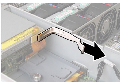
FIGURE 3-47 Removing the Upper Cable Retaine

9. Remove the upper cable retainer from the chassis. Push the retainer toward the rear of the chassis to free it from the keyed openings in the chassis midwall. See FIGURE 3-47.
10. Disconnect the flex cable connectors from the rear of the DVD-ROM drive and the drives backplane. See FIGURE 3-48.
FIGURE 3-48 Disconnecting the Flex Cable From the DVD Drive and the Drives Backplane

a. Pull the spring latch at the front of the DVD-ROM drive to the left and hold it. See FIGURE 3-49.
b. Use your other hand to reach behind the drive and push it out through the front of the chassis.
FIGURE 3-49 Removing the DVD-ROM Drive
12. Unfasten the screws that secure the drives backplane to the rear of the drive bays. See FIGURE 3-50.
13. Remove the drives backplane from the chassis.
FIGURE 3-50 Removing the Drives Backplane

Installation is the reverse of this procedure. When reinstalling screws, tighten to 7 in-lbs (0.8 Nm) using an adjustable torque driver.
| Note - Sun Fire X4100/X4200 servers use only DDR1 DIMM.
Sun Fire X4100 M2/X4200 M2 servers use only DDR2 DIMMs. |
| Note - Do not mix single-rank and dual-rank pairs on a CPU memory bank or there will be a 10% loss in performance. |
| Note - If you are installing single-rank DIMMs, be sure to upgrade the system BIOS to the latest version. |
| Note - Do not mix single-rank DIMMs and dual-rank DIMMs within a pair. |
The DIMM population rules for Sun Fire X4100/X4200 servers are as follows:
| Note - The system reports individual DIMM numbers when a memory fault happens. |
The DIMM population rules for Sun Fire X4100 M2/X4200 M2 servers are listed here:
| Note - The system reports individual DIMM numbers when a memory fault happens. |
Before installing DIMMs into a single-CPU system, ensure they meet the following requirements:
For information on determining if your system has one or two CPUs, see HT Jumper Configuration for Single-CPU Servers (Sun Fire X4100 M2 and X4200 M2).
| Note - Sun Fire X4200 servers use only DDR1 DIMMs.
Sun Fire X4200 M2 servers use only DDR2 DIMMs. |
| Note - This component is a CRU. |
If you are installing DIMMs into a single-CPU system, see Installing DIMMs Into a Single-CPU System before beginning your DIMMs installation.
Supported components and their part numbers are subject to change over time. For the most up-to-date list of replaceable components for these servers, refer to:
http://sunsolve.sun.com/handbook_pub/Systems
1. Click the name and model of your server.
2. On the product page that opens for the server, click Full Components List to view a list of components.
Use the following procedure to replace server’s dual, in-line memory modules (DIMMs).
The following are a list of DIMMs supported on the X4100/X4100 M2 and X4200/X4200 M2 systems.
Note - For information on the incompatibility of some Micron DIMMs with the quad-core processor, see the Sun Fire X4100 M2/X4200 M2 Servers Product Notes. X4100 M2/X4200 M2 Servers Product Notes.
|
To replace DIMMs, do the following:
1. Power off the server as described in Powering Off the Server.
2. If the server is in a rack, slide it far enough from the rack so that you can remove the main cover. If you cannot safely view and access the component, remove the server from the rack.
3. Remove the main cover as described in Removing the Main Cover of the Sun Fire X4100/X4100 M2 Server or Removing the Main Cover of the Sun Fire X4200/X4200 M2 Servers.
4. Locate the DIMM slot on the motherboard to which you will install or replace a DIMM.
The DIMM ejector levers contain LEDs that can indicate a faulty DIMM:
Note the following differences between servers regarding the power requirements for viewing the DIMM fault LEDs:
FIGURE 3-51 DIMM Slot Numbering and Pairing - Sun Fire X4100/X4200

FIGURE 3-52 DIMM Slot Numbering and Pairing - Sun Fire X4100 M2/X4200 M2

5. Before continuing with the next step, review DIMM Population Rules.
a. Rotate both DIMM slot ejectors outward as far as they will go. The DIMM is partially ejected from the socket. See FIGURE 3-53.
b. Carefully lift the DIMM straight up to remove it from the socket.

| Note - The Sun Fire X4200 server uses only DDR1 DIMMs. The Sun Fire X4200 M2 server uses only DDR2 DIMMs. |
a. Ensure that the DIMM slot ejectors at each end of the memory socket are fully open (rotated outward) to accept the new DIMM.
b. Align the notch in the bottom edge of the DIMM with the key in the DIMM socket. See FIGURE 3-53.
c. Press down evenly on both top corners of the DIMM until the ejectors snap over the cutouts in the left and right edges of the DIMM.

8. If you installed 4-GB DIMMs in a Sun Fire X4100/X4200 server that did not previously have 4-GB DIMMs installed, install gaskets on the main cover.
| Note - This gasket installation does not apply to Sun Fire X4100 M2/X4200 M2 servers. |
a. Remove the backing strip from the adhesive on one of the new gaskets.
b. Set the new gasket in place, being careful to align the end of the gasket with the front edge of the main cover. See FIGURE 3-54.
c. Press down on the gasket to remove any trapped air and secure it firmly to the main cover.
d. Install the remaining gasket to the main cover.
FIGURE 3-54 Installing a Main Cover Gasket for 4-GB DIMMs

| Note - Sun Fire X4200 servers support only PCIX style cards; Sun Fire X4200 M2 servers support one PCIX slot and four PCI-Express (PCIE) slots. |
| Note - This component is a CRU and can be replaced by anyone. |
Supported components and their part numbers are subject to change over time. For the most up-to-date list of replaceable components for these servers, refer to:
http://sunsolve.sun.com/handbook_pub/Systems
1. Click the name and model of your server.
2. On the product page that opens for the server, click Full Components List to view a list of components.
Use the following procedure to replace a PCI card.
1. Power off the server as described in Powering Off the Server.
2. If the server is in a rack, slide it far enough from the rack so that you can remove the main cover. If you cannot safely view and access the component, remove the server from the rack.
3. Remove the main cover as described in Removing the Main Cover of the Sun Fire X4100/X4100 M2 Server or Removing the Main Cover of the Sun Fire X4200/X4200 M2 Servers.
4. Locate the PCI card slot in which you will install or replace a PCI card.
The system designation and the speeds of the five PCI slots are shown in FIGURE 3-56 and FIGURE 3-57.
The slots for the PCI cards are detected by the system BIOS during bootup in the order described in PCI Card Slot Boot Priority.
| Note - Sun Fire X4100/X4100 M2 only: The server is shipped with two PCI risers already installed in the low-profile PCI card sockets. |
| Note - Before you install a card, consult the manufacturer's documentation for system requirements and configuration information for your specific PCI card. |
FIGURE 3-55 Designation and Speeds of PCI Slots - Sun Fire X4100/X4100 M2

FIGURE 3-56 Designation and Speeds of PCI Slots - Sun Fire X4200

FIGURE 3-57 Designation and Speeds of PCI Slots - Sun Fire X4200 M2

5. Remove the slot cover or PCI card from the slot. See FIGURE 3-58 or FIGURE 3-59.
a. Disconnect any external cables that are attached to the PCI card.
b. Working from the rear of the chassis, pivot open the PCI card latch that covers the PCI card’s rear connector panel.
c. Pull the PCI cards or slot covers out of the PCI slots. Ensure that each PCI card's rear connector panel is released from the tabs on the chassis rear panel.
FIGURE 3-58 Opening a PCI Card Securing Latch (Sun Fire X4200/X4200 M2 Server Shown)

FIGURE 3-59 Opening a PCI Card Securing Latch (Sun Fire X4100/X4100 M2 Server Shown)

| Note - Sun Fire X4200 servers support only PCIX style cards; Sun Fire X4200 M2 servers support one PCIX slot and four PCI-Express (PCIE) slots. |
a. Insert the PCI card into the PCI card slot. Ensure that the PCI card's rear connector panel engages the tab in the chassis rear panel.
b. Pivot the PCI card latch closed over the rear connector panel of the PCI card until it locks. See FIGURE 3-60 or FIGURE 3-61.
FIGURE 3-60 Installing a PCI Card (Sun Fire X4200/X4200 M2 Server Shown)

FIGURE 3-61 Installing a PCI Card (Sun Fire X4100 M2 Server Shown)

| Note - Sun Fire X4100/X4200 and X4100 M2/X4200 M2 servers use different motherboards. Do not interchange them. |
| Note - This component is an FRU and should be replaced only by qualified service technicians. Contact your Sun Service representative for assistance. |
Supported components and their part numbers are subject to change over time. For the most up-to-date list of replaceable components for these servers, refer to:
http://sunsolve.sun.com/handbook_pub/Systems
1. Click the name and model of your server.
2. On the product page that opens for the server, click Full Components List to view a list of components.
Use the following procedure to remove and replace the motherboard.
1. Power off the server as described in Powering Off the Server.
2. If the server is in a rack, remove the server from the rack.
3. Remove the main cover as described in Removing the Main Cover of the Sun Fire X4100/X4100 M2 Server or Removing the Main Cover of the Sun Fire X4200/X4200 M2 Servers.
4. Remove the front bezel as described in Removing the Front Bezel of the Sun Fire X4100/X4100 M2 Server or Removing the Front Bezel of the Sun Fire X4200/X4200 M2 Servers.
| Note - Always unfasten the bezel’s securing screw before removing the bezel. |
5. Remove the front cover as described in Removing the Front Cover of the Sun Fire X4100/X4100 M2 Server or Removing the Front Cover of the Sun Fire X4200/X4200 M2 Servers.
a. Disconnect any external cables from the PCI cards.
b. Working from the rear of the chassis, pivot each card latch to release the PCI cards. See FIGURE 3-58 and Opening a PCI Card Securing Latch (Sun Fire X4100/X4100 M2 Server Shown).
c. Pull the PCI cards out of the PCI slots. Ensure that each PCI card's rear connector panel is released from the tabs on the chassis rear panel.
7. Sun Fire X4200/X4200 M2 Only: Pivot the PCI card latches back to their closed positions.
8. Remove the Graphics Redirect and Service Processor (GRASP) board, as described in Replacing the Graphics Redirect and Service Processor (GRASP) Board.
9. Remove all DIMMs from the motherboard. For details, see Replacing DIMMs.
10. Remove all CPUs from the motherboard.
Refer to one of the following procedures, depending on your model of the server:
11. Disconnect and remove the interconnect cable that connects the motherboard and the front I/O board. See FIGURE 3-62 and FIGURE 3-63.
FIGURE 3-62 Disconnecting the Front I/O Interconnect Cable (Sun Fire X4100/X4100 M2 Server Shown)

FIGURE 3-63 Disconnecting the Front I/O Interconnect Cable (Sun Fire X4200/X4200 M2 Server Shown)

12. Unfasten the spring-loaded thumbscrew that secures the flex cable retainer and remove this retainer from the chassis. See Removing the Flex Cable Retainer.
13. Remove the upper cable retainer from the chassis. Push the retainer toward the rear of the chassis to free it from the keyed openings in the chassis midwall. See Removing the Upper Cable Retaine.
14. Remove the flex cable and its attached foam rubber gasket from the chassis inner wall by disconnecting the cable’s four connectors from the following four locations. See FIGURE 3-64.
| Note - When reinstalling the flex cable, attach the connector to the power distribution board (3) first. Then attach the remaining three connectors in any order. |
FIGURE 3-64 Disconnecting the Flex Cable’s Four Connectors (Sun Fire X4200/X4200 M2 Server Shown)

15. Unfasten and remove the eight screws that secure the motherboard to the chassis floor. See FIGURE 3-65 for the location of the eight screws.
16. Use an 8-mm nut-driver to remove the two bus-bar nuts from the motherboard. See FIGURE 3-65.
FIGURE 3-65 Motherboard Securing Screw and Bus-Bar Nut Locations (Sun Fire X4200/X4200 M2 Server Shown)

17. Use the lifting handle to raise the forward edge of the board until it has cleared the bus bar studs.
|
|
Caution - When lifting the board, use caution to avoid damaging the light pipes and connectors on the rear edge of the motherboard. |
18. Slide the board toward the front of the chassis until the connectors and light pipes are clear of the chassis back panel. Then raise the motherboard and remove it from the chassis.
Installation is the reverse of this procedure. Note the following:
|
|
Caution - When reinstalling the CPUs, follow the instructions in Replacing a CPU and Heatsink (Sun Fire X4100 and X4200 Servers)or Replacing a CPU and Heatsink (Sun Fire X4100 M2/X4200 M2 Servers). |
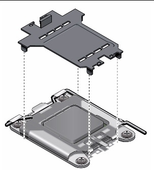
| Note - When you replace your motherboard, you must take the plastic CPU socket covers that are present on the new replacement motherboard and install them into the CPU sockets of the old motherboard before shipping. This ensures that the CPU pins are not damaged in transit. See FIGURE 3-66. |
FIGURE 3-66 Installing the CPU Socket Protective Cover
DC power supplies can be ordered as a factory installed option, or they can be ordered and used to replace existing AC power supplies in the field.
|
|
Caution - Do not mix AC and DC power supplies in the same server. |
| Note - This component is a hot-swappable CRU and can be replaced by anyone. |
Supported components and their part numbers are subject to change over time. For the most up-to-date list of replaceable components for these servers, refer to:
http://sunsolve.sun.com/handbook_pub/Systems
1. Click the name and model of your server.
2. On the product page that opens for the server, click Full Components List to view a list of components.
Use the following procedure to remove and replace a power supply.
The system designation of the two power supplies is shown in FIGURE 3-67 and FIGURE 3-68.
FIGURE 3-67 Designation of Power Supplies (Sun Fire X4200/X4200 M2 Server Shown)

FIGURE 3-68 Designation of Power Supplies (Sun Fire X4100/X4100 M2 Server Shown)

1. Identify which power supply you will replace. Each power supply has three LEDs that you can view from the rear of the server:
2. Disconnect the power cord from the power supply that you are replacing.
The power supplies are hot-swappable, so you do not have to shut down the server or disconnect the second power supply.
| Note - The Service Action Required LEDs on the front panel and back panel blink when a power supply is unplugged. See External Status Indicator LEDs for the LED locations and descriptions. |
a. Grasp the power supply handle and push the thumb latch toward the center of the power supply. See FIGURE 3-69.
b. While continuing to push on the latch, use the handle to remove the power supply from the chassis.
FIGURE 3-69 Removing a Power Supply (Sun Fire X4200/X4200 M2 Server Shown)

Installation is the reverse of this procedure.
| Note - When installing a new power supply, press it into the bay until the thumb latch clicks, indicating that it is locked. |
| Note - This component is an FRU and should be replaced only by qualified service technicians. Contact your Sun Service representative for assistance. |
Supported components and their part numbers are subject to change over time. For the most up-to-date list of replaceable components for these servers, refer to:
http://sunsolve.sun.com/handbook_pub/Systems
1. Click the name and model of your server.
2. On the product page that opens for the server, click Full Components List to view a list of components.
Use the following procedure to replace the PDB.
1. Power off the server as described in Powering Off the Server.
2. If the server is in a rack, slide it far enough from the rack so that you can remove the main cover and front cover. If you cannot safely view and access the component, remove the server from the rack.
3. Remove the main cover as described in Removing the Main Cover of the Sun Fire X4100/X4100 M2 Server or Removing the Main Cover of the Sun Fire X4200/X4200 M2 Servers.
4. Remove the front bezel as described in Removing the Front Bezel of the Sun Fire X4100/X4100 M2 Server or Removing the Front Bezel of the Sun Fire X4200/X4200 M2 Servers.
| Note - Always unfasten the bezel’s securing screw before removing the bezel. |
5. Remove the front cover as described in Removing the Front Cover of the Sun Fire X4100/X4100 M2 Server or Removing the Front Cover of the Sun Fire X4200/X4200 M2 Servers.
6. Remove both power supplies:
a. Grasp the power supply handle and push the thumb latch toward the center of the power supply. See Removing a Power Supply (Sun Fire X4200/X4200 M2 Server Shown).
b. While continuing to push on the latch, use the handle to remove the power supply from the chassis.
7. Unfasten the spring-loaded thumbscrew that secures the flex cable retainer and remove this retainer from the chassis. See Removing the Flex Cable Retainer.
8. Remove the upper cable retainer from the chassis. Push the retainer toward the rear of the chassis to free it from the keyed openings in the chassis midwall. See Removing the Upper Cable Retaine.
9. Remove the flex cable and its attached foam rubber gasket from the chassis midwall by disconnecting the cable’s four connectors from the following four locations. See Disconnecting the Flex Cable From the DVD Drive and the Drives Backplane.
c. Power distribution board (see note below)
| Note - When reinstalling the flex cable, attach the connector to the power distribution board (item 3 above) first. Then attach the remaining three connectors in any order. |
10. Sun Fire X4200/X4200 M2 Only: Disconnect the rear fan tray cable from the connector on the power distribution board. See FIGURE 3-70.
FIGURE 3-70 Disconnecting the Rear Fan Tray From the Power Distribution Board

11. Use a No. 2 Phillips screwdriver to remove the three screws that secure the power distribution board to the chassis and bus bars. See FIGURE 3-71.
FIGURE 3-71 Disconnecting the Power Distribution Board From the Chassis

12. Raise the plastic air baffles that cover the power supply connectors up and toward the rear of the chassis to provide clearance.
13. Slide the power distribution board toward the front of the chassis to release the five chassis standoffs from the keyways in the board.
14. Lift the board up off of the chassis standoffs and remove it from the chassis.
FIGURE 3-72 Removing the Power Distribution Board

Installation is the reverse of this procedure. Note the following:
| Note - This component is a hot-swappable CRU and can be replaced by anyone. |
Supported components and their part numbers are subject to change over time. For the most up-to-date list of replaceable components for these servers, refer to:
http://sunsolve.sun.com/handbook_pub/Systems
1. Click the name and model of your server.
2. On the product page that opens for the server, click Full Components List to view a list of components.
Use the following procedure to remove and replace the rear fan tray.
1. Working from the rear of the server, unfasten the two captive thumbscrews on the face of the rear fan tray. See FIGURE 3-73
The internal system software designation of the rear fan tray is FT3. The rear fan tray has one fault LED on its face:
2. Remove the rear fan tray from the chassis.
The fan tray’s cable connector disengages from the internal connector on the chassis.
| Note - In FIGURE 3-73, the server is shown with the cover off for visibility of the component; do not remove the cover for this procedure. |
FIGURE 3-73 Removing the Rear Fan Tray

Installation is the reverse of this procedure.
| Note - When you reinstall the new rear fan tray, ensure that the metal guides on the fan tray sides (see FIGURE 3-73) engage the plastic rails inside the chassis bay evenly. |
| Sun Fire X4100/X4100 M2 and X4200/X4200 M2 Servers Service Manual | 819-1157-23 |
Copyright © 2009 Sun Microsystems, Inc. All rights reserved.
