This appendix contains information about the locations and behavior of the LEDs on the server. It describes the external LEDs that can be viewed on the outside of the server and the internal LEDs that can be viewed only with the main cover removed.
External Status Indicator LEDs
See the following figures and tables for information about the LEDs that are viewable on the outside of the server.
Front Panel LEDs
FIGURE B-1 Sun Fire X4150 Server Front Panel LEDs
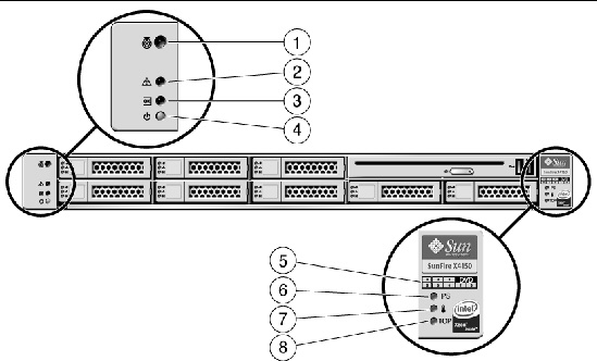
Figure Legend
|
1
|
Locator LED/Locator button: (White)
|
5
|
Hard drive map
|
|
2
|
Service Required LED: (Amber)
|
6
|
Rear PS LED: (Amber) Power supply fault
|
|
3
|
Power/OK LED: (Green)
|
7
|
System Over Temperature LED: (Amber)
|
|
4
|
Power button
|
8
|
Top Fan LED: (Amber) Service action required on fans
|
FIGURE B-2 Sun Fire X4250 Server Front Panel LEDs

FIGURE B-3 Sun Fire X4450 Server Front Panel LEDs
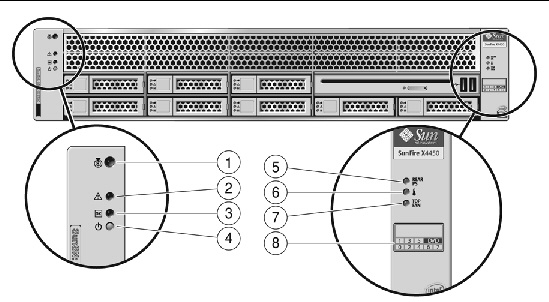
Figure Legend (applies to both X4250 and X4450)
|
1
|
Locator LED/Locator button: (White)
|
5
|
Rear PS LED: (Amber) Power supply fault
|
|
2
|
Service Required LED: (Amber)
|
6
|
System Over Temperature LED: (Amber)
|
|
3
|
Power/OK LED: (Green)
|
7
|
Top Fan LED: (Amber) Service action required on fans
|
|
4
|
Power button
|
8
|
Hard drive map
|
Back Panel LEDs
FIGURE B-4 Sun Fire X4150 Server Back Panel LEDs
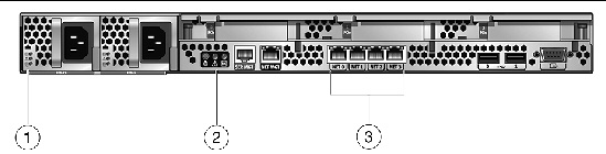
FIGURE B-5 Sun Fire X4250 and X4450 Server Back Panel LEDs

Figure Legend (applies to all servers)
|
1
|
Power Supply LEDs:
|
3
|
Ethernet Port LEDs
|
|
|
|
|
Left side: Green indicates link activity
|
|
|
- Power Supply Fail: (Amber)
|
|
Right side:
|
|
|
|
|
- Green: Link is operating at maximum speed
|
|
2
|
System LEDs
|
|
- Amber: Link is operating at less than maximum speed.
|
|
|
- Locator LED Button: (White)
|
|
|
|
|
- Service Required LED: (Amber)
|
|
|
|
|
|
|
|
Hard Drive LEDs
FIGURE B-6 Hard Drive LEDs
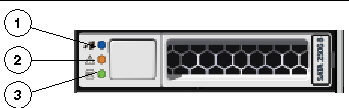
Figure Legend
|
1
|
Ready to remove LED: Blue - Service action is allowed
|
|
2
|
Fault LED: Amber - Service action is required
|
|
3
|
Status LED: Green - Blinks when data is being transferred
|
Internal Status Indicator LEDs
The server has internal status indicators on the motherboard.
- The DIMM Fault LEDs indicate a problem with the corresponding DIMM. See FIGURE B-7 and FIGURE B-8 for the LED locations.
When you press the Remind button, if there is a problem with a DIMM, the corresponding DIMM Fault LED flashes. See DIMM Fault LEDs for details.
- The CPU Fault LEDs indicate a problem with the corresponding CPU. See FIGURE B-9 and FIGURE B-10 for the CPU LED locations.
When you press the Remind button, if there is a problem with a CPU, the corresponding CPU Fault LED flashes.
| Note - The DIMM Fault and CPU Fault LEDs operate on stored power for up to a minute when the system is powered down, even after the AC power is disconnected, and the motherboard is out of the system. The stored power lasts for about half an hour.
|
FIGURE B-7 Remind Button and DIMM LEDs on X4150 and X4250 Motherboard

FIGURE B-8 Remind Button and DIMM LEDs on X4450 Motherboard

FIGURE B-9 Remind Button and CPU LEDs on X4150 and X4250 Motherboard

FIGURE B-10 Remind Button and CPU LEDs on X4450 Motherboard

| Sun Fire X4150, X4250, and X4450 Servers Diagnostics Guide
|
820-4213-11
|
   
|
Copyright © 2009 Sun Microsystems, Inc. All rights reserved.