| Sun Fire X4250 Server Service Manual |
| C H A P T E R 4 |
|
Servicing Motherboard Components |
This chapter describes how to replace the motherboard and its components in the Sun Fire X4250 server.
| Note - Before performing any of the procedures in this chapter, perform the procedures described in Chapter 2, Preparing to Service the System. |
The following topics are covered in this chapter:
| Note - Never attempt to run the server with the covers removed. Hazardous voltage is present. |

|
Caution - Equipment damage is possible. The covers must be in place for proper air flow. |
This section describes how to diagnose and replace faulty FB-DIMMs (fully buffered DIMMs). The following topics are covered:
Refer to the Sun Fire X4150, X4250, and X4450 Servers Diagnostics Guide for additional DIMM troubleshooting information.
| Note - This is a customer-replaceable unit. |
|
|
Caution - This procedure requires that you handle components that are sensitive to static discharge. This sensitivity can cause the component to fail. To avoid damage, ensure that you follow antistatic practices as described in Section 2.7.1, Electrostatic Discharge Safety Measures. |
The Sun Fire X4250 Service Required LED is lit if the system detects a FB-DIMM fault.
1. Prepare the server for service.
See Section 2.4, Powering Off the Server.
b. Disconnect the power cord (or cords) from the power supply (or supplies).
See Section 2.4, Powering Off the Server.
c. Slide the server out of the rack.
See Section 2.5, Extending the Server to the Maintenance Position.
d. Attach an antistatic wrist strap.
See Section 2.7, Performing Electrostatic Discharge and Antistatic Prevention Measures.
See Section 2.8, Removing the Top Cover.
2. Press and hold the Remind button to identify which FB-DIMM is faulty. (FIGURE 4-1)
3. Note the location of faulty FB-DIMMs.
Faulty FB-DIMMs are identified with a corresponding amber LED on the motherboard.
4. Ensure that all FB-DIMMs are seated correctly in their slots.
If re-seating the FB-DIMM does not fix the problem, remove and replace the faulty FB-DIMM.
| Note - Refer to the Sun Fire X4150, X4250, and X4450 Servers Diagnostics Guide for more information about DIMM System Event Log (SEL) messages. |
FIGURE 4-1 Remind Button Locations

Use the FB-DIMM guidelines, and FIGURE 4-2 to help you plan the memory configuration of your server.
Any even number of DIMMs is allowed. The DIMMs must be populated in pairs and the pairs must be identical in organization, size and speed. See FIGURE 4-2 for detailed configuration information.


|
Caution - Ensure that all power is removed from the server before removing or installing FB-DIMMs. You must disconnect the power cables before performing this procedure. |
1. Review Section 4.1.2, FB-DIMM Guidelines for memory configuration information.
2. Prepare the server for service.
See Section 2.4, Powering Off the Server.
b. Disconnect the power cord (or cords) from the power supply (or supplies).
See Section 2.4, Powering Off the Server.
c. Slide the server out of the rack.
See Section 2.5, Extending the Server to the Maintenance Position.
d. Attach an antistatic wrist strap.
See Section 2.7, Performing Electrostatic Discharge and Antistatic Prevention Measures.
See Section 2.8, Removing the Top Cover.
3. Lift up the air duct. (FIGURE 4-3 [1])
4. If you are replacing a faulty FB-DIMM, press the Remind button on the motherboard to locate the FB-DIMMS that you want to replace.
The faulty FB-DIMM LED flashes when the Fault Remind button is pressed and held. All faulty FB-DIMMs are indicated with an amber LED, so that you can install the replacement FB-DIMM in the same location.
| Tip - Make a note of the faulty FB-DIMM location. |
5. Push down on the ejector tabs on each side of the FB-DIMM until the FB-DIMM is released. [2]
6. Grasp the top corners of the faulty FB-DIMM and remove it from the server.
.")
7. Place the FB-DIMM on an antistatic mat.
8. Repeat Step 5 through Step 7 to remove any additional FB-DIMMs.
| Tip - See Section 4.1.2, FB-DIMM Guidelines for information about configuring the FB-DIMMs. |
1. Unpackage the replacement FB-DIMMs and place them on an antistatic mat.
2. Ensure that the ejector tabs are in the open position.
3. Line up the replacement FB-DIMM with the connector (FIGURE 4-4).
Align the FB-DIMM notch with the key in the connector. This ensures that the FB-DIMM is oriented correctly.
4. Push the FB-DIMM into the connector until the ejector tabs lock the FB-DIMM in place.
If the FB-DIMM does not easily seat into the connector, verify that the orientation of the FB-DIMM is as shown in FIGURE 4-4. If the orientation is reversed, damage to the FB-DIMM might occur.
5. Repeat Step 2 through Step 4 until all replacement FB-DIMMs are installed.
6. Replace the air duct to the down position.
See Section 6.1, Installing the Top Cover.
8. Slide the server into the rack.
See Section 6.3, Returning the Server to the Normal Rack Position.
9. Reconnect the power cord (or cords) to the power supply (or supplies).
Verify that the AC Present LED is lit.
See Section 6.4, Powering On the Server.
See Section 6.4, Powering On the Server.
FIGURE 4-4 Installing FB-DIMMs
.")
Before you begin, see Section 4.1.2, FB-DIMM Guidelines, for information about FB-DIMM configuration guidelines.
1. Unpackage the replacement FB-DIMMs and place them on an antistatic mat.
2. Ensure that the ejector tabs are in the open position.
3. Line up the FB-DIMM with the connector (FIGURE 4-4).
Align the FB-DIMM notch with the key in the connector. This ensures that the FB-DIMM is oriented correctly.
4. Push the FB-DIMM into the connector until the ejector tabs lock the FB-DIMM in place.
If the FB-DIMM does not easily seat into the connector, verify that the orientation of the FB-DIMM is as shown in FIGURE 4-3. If the orientation is reversed, damage to the FB-DIMM might occur.
5. Repeat Step 2 through Step 4 until all FB-DIMMs are installed.
6. Replace the air duct to the down position.
See Section 6.1, Installing the Top Cover.
8. Slide the server into the rack.
See Section 6.3, Returning the Server to the Normal Rack Position.
9. Reconnect the power cord (or cords) to the power supply (or supplies).
Verify that the AC Present LED is lit.
See Section 6.4, Powering On the Server.
See Section 6.4, Powering On the Server.
You must remove the air duct when removing and installing the following components:
| Note - This is a customer-replaceable unit. |
|
|
Caution - To prevent the system from overheating, ensure that the air duct is correctly installed before powering on the server. |
1. Prepare the server for service.
See Section 2.4, Powering Off the Server.
b. Disconnect the power cord (or cords) from the power supply (or supplies).
See Section 2.4, Powering Off the Server.
c. Slide the server out of the rack.
See Section 2.5, Extending the Server to the Maintenance Position.
d. Attach an antistatic wrist strap.
See Section 2.7, Performing Electrostatic Discharge and Antistatic Prevention Measures.
See Section 2.8, Removing the Top Cover.
2. Slide the air duct to the right to disengage the left hand pin as shown in FIGURE 4-5.
3. Slide the air duct to the left to disengage the right hand pin.
4. Move the air duct towards the back to clear the lip on the midwall.
5. Lift the air duct out of the server.
FIGURE 4-5 Removing the Air Duct
.")
|
|
Caution - When the server is in operation, ensure that the air duct is correctly installed to prevent the system from overheating. |
1. Install the air duct into the chassis as shown in FIGURE 4-6.
Ensure that the air duct is aligned and fully seated in the chassis.
2. Move the air duct towards the front.
3. Slide the air duct to the left to engage the right-hand pin.
4. Slide the air duct to the right to engage the left-hand pin.
5. Return the server to operation.
See Section 6.1, Installing the Top Cover.
b. Slide the server into the the rack.
See Section 6.3, Returning the Server to the Normal Rack Position.
c. Reconnect the power cord (or cords) to the power supply (or supplies).
Verify that the AC Present LED is lit.
See Section 6.4, Powering On the Server.
See Section 6.4, Powering On the Server.
FIGURE 4-6 Installing the Air Duct
.")
PCIe cards are installed on vertical risers. You must remove the relevant riser to access a PCIe card. You must remove all three PCIe risers when replacing the motherboard.
| Note - This is a customer-replaceable unit. |
|
|
Caution - This procedure requires that you handle components that are sensitive to static discharge. This sensitivity can cause the component to fail. To avoid damage, ensure that you follow antistatic practices as described in Section 2.7.1, Electrostatic Discharge Safety Measures. |
|
|
Caution - Ensure that all power is removed from the server before removing or installing risers. You must disconnect the power cables before performing this procedure. |
1. Prepare the server for service.
See Section 2.4, Powering Off the Server.
b. Disconnect the power cord (or cords) from the power supply (or supplies).
See Section 2.4, Powering Off the Server.
c. Attach an antistatic wrist strap.
See Section 2.7, Performing Electrostatic Discharge and Antistatic Prevention Measures.
d. Disconnect any data cables connected to the cards on the PCIe riser being removed.
Label the cables to ensure proper connection later.
e. Slide the server out of the rack.
See Section 2.5, Extending the Server to the Maintenance Position.
See Section 2.8, Removing the Top Cover.
2. If you are servicing a PCIe card, locate its position in the system.
3. Disconnect any data cables connected to the cards on the PCIe riser being removed.
Label the cables to ensure proper connection later.
4. Remove the rear panel PCI cross beam. (FIGURE 4-7) [1]
a. Loosen the two captive Phillips screws on the end of the PCI cross beam.
b. Lift the PCI cross beam up and back to remove it from the chassis.
5. Loosen the captive retaining screw holding the front end of the riser to the motherboard. [2]
6. Lift the riser up to remove it from the server.
Remove the riser and any PCIe cards attached to it as a unit.
FIGURE 4-7 Removing a PCIe Riser
.")
|
|
Caution - Ensure that all power is removed from the server before removing or installing risers. You must disconnect the power cables before performing this procedure. |
1. Lower the PCIe riser and any cards attached to it into the system. (FIGURE 4-8 [1])
2. Slide the back of the riser into the motherboard rear panel stiffener.
3. Tighten the screw that secures the riser to the motherboard.
4. Install the rear panel PCI cross beam. [2]
a. Slide the cross beam down over the PCIe risers.
b. Secure the PCI cross beam with two captive Phillips screws.
5. Return the server to operation.
See Section 6.1, Installing the Top Cover.
b. Connect any data cables to the PCIe card.
Route data cables through the cable management arm.
c. Slide the server into the rack.
See Section 6.3, Returning the Server to the Normal Rack Position.
d. Reconnect the power cord (or cords) to the power supply (or supplies).
Verify that the AC Present LED is lit.
See Section 6.4, Powering On the Server.
See Section 6.4, Powering On the Server.
FIGURE 4-8 Installing a PCIe Riser
.")
See Section 4.4.1, Sun Fire X4250 PCIe Card Guidelines for PCIe card configuration guidelines. The following topics are covered:
|
|
Caution - This procedure requires that you handle components that are sensitive to static discharge. This sensitivity can cause the component to fail. To avoid damage, ensure that you follow antistatic practices as described in Section 2.7, Performing Electrostatic Discharge and Antistatic Prevention Measures. |
|
|
Caution - Ensure that all power is removed from the server before removing or installing expansion cards. You must disconnect the power cables before performing this procedure. |
The PCI expansion system is configured using a variety of riser cards. The connector is an x16 but the cards may operate at x8. All connectors operate at x8 and the active riser x8 slots share a single x8.
FIGURE 4-9 Identifying PCIe Cards

|
|
Caution - Ensure that all power is removed from the server before removing or installing expansion cards. You must disconnect the power cables before performing this procedure. |
1. Prepare the server for service.
See Section 2.4, Powering Off the Server.
b. Disconnect the power cord (or cords) from the power supply (or supplies).
See Section 2.4, Powering Off the Server.
c. Slide the server out of the rack.
See Section 2.5, Extending the Server to the Maintenance Position.
d. Attach an antistatic wrist strap.
See Section 2.7, Performing Electrostatic Discharge and Antistatic Prevention Measures.
See Section 2.8, Removing the Top Cover.
2. Locate the PCIe card that you want to remove, and note its corresponding riser board.
See Section 1.4, Sun Fire X4250 Server Rear Panel Features for more information about PCIe slots and their locations.
3. If necessary, make a note of where the PCIe cards are installed.
4. Unplug all data cables from the card.
Note the location of all cables for reinstallation later.
5. Remove the rear panel crossbeam and then the riser board. (FIGURE 4-10)
See Section 4.3, Servicing PCIe Risers.
6. Carefully remove the PCIe card from the riser board connector.
7. Place the PCIe card on an antistatic mat.
8. If you are not replacing the PCIe card, install a PCIe filler panel.
PCIe filler panels are located in the motherboard rear panel.
FIGURE 4-10 Removing a PCIe Card
.")
|
|
Caution - Ensure that all power is removed from the server before removing or installing expansion cards. You must disconnect the power cables before performing this procedure. |
1. Unpack the replacement PCIe card and place it on an antistatic mat.
2. Locate the proper PCIe slot for the card you are replacing.
3. If necessary, review the PCIe Card Guidelines to plan your installation.
See Section 4.4.1, Sun Fire X4250 PCIe Card Guidelines for additional information.
4. Remove the PCIe riser board.
See Section 4.3, Servicing PCIe Risers.
5. If the server has been continously used for an extended time, inspect the slot for particles.
Clean the slot with filtered, compressed air, as required.
6. Remove the PCI filler panel.
PCIe filler panels are located in the motherboard rear panel.
7. Insert the PCIe card into the correct slot on the riser board. (FIGURE 4-11)
a. Slide the riser back until it seats in its slot in the rear panel.
b. Tighten the captive No. 2 Phillips screw securing the riser to the motherboard.
See Section 6.1, Installing the Top Cover.
10. Slide the server into the rack.
See Section 6.3, Returning the Server to the Normal Rack Position.
11. Connect any required data cables to the PCIe card.
Route data cables through the cable management arm.
12. Reconnect the power cord (or cords) to the power supply (or supplies).
Verify that the AC Present LED is lit.
See Section 6.4, Powering On the Server.
See Section 6.4, Powering On the Server.
FIGURE 4-11 Installing a PCIe Card
.")
The battery maintains system time when the server is powered off and a time server is unavailable. If the server fails to maintain the proper time when powered off and not connected to a network, replace the battery. (FIGURE 4-12)
You need a small (No. 1 flat-blade) non-metallic screwdriver or equivalent.
|
|
Caution - Ensure that all power is removed from the server before removing or installing the battery. You must disconnect the power cables from the system before performing this procedure. |

1. Prepare the server for service.
See Section 2.4, Powering Off the Server.
b. Disconnect the power cord (or cords) from the power supply (or supplies).
See Section 2.4, Powering Off the Server.
c. Slide the server out of the rack.
See Section 2.5, Extending the Server to the Maintenance Position.
d. Attach an antistatic wrist strap.
See Section 2.7, Performing Electrostatic Discharge and Antistatic Prevention Measures.
See Section 2.8, Removing the Top Cover.
2. Remove the PCIe riser closest to the power supply.
See Section 4.3.1, Removing a PCIe Riser.
See Section 4.4.1, Sun Fire X4250 PCIe Card Guidelines.
3. Press the latch and remove the battery from the motherboard.
Use a small (No. 1 flat-blade) non-metallic screwdriver or equivalent.
1. Unpack the replacement battery.
2. Press the new battery into the motherboard.
Install the positive side (+) facing upward, away from the motherboard.
3. Install PCIe riser 0 with any associated cards.
See Section 4.3.2, Installing a PCIe Riser.
4. Return the server to operation.
See Section 6.1, Installing the Top Cover.
b. Slide the server into the the rack.
See Section 6.3, Returning the Server to the Normal Rack Position.
c. Reconnect the power cord (or cords) to the power supply (or supplies).
Verify that the AC Present LED is lit.
See Section 6.4, Powering On the Server.
See Section 6.4, Powering On the Server.
5. Use the ILOM set date command to set the day and time.
See the Integrated Lights Out Management Guide.
The following topics are covered:
You must remove the motherboard assembly to access the following components:
| Note - FRU: This field-replaceable unit should be replaced only by qualified service technicians. Contact your Sun Service representative for assistance. |
|
|
Caution - This procedure requires that you handle components that are sensitive to electrostatic discharge. This discharge can cause server components to fail. To avoid damage, ensure that you follow the antistatic practices as described in Section 2.7, Performing Electrostatic Discharge and Antistatic Prevention Measures. |
|
|
Caution - This procedure requires removing the server from the rack. The server is heavy. Two people are required to remove it from the rack. |
You need a No. 2 Phillips screwdriver.
1. Prepare the server for service.
See Section 2.4, Powering Off the Server.
b. Disconnect the power cord (or cords) from the power supply (or supplies).
See Section 2.4, Powering Off the Server.
c. Remove the server from the rack.
See Section 2.6, Removing a Server From the Rack..
d. Attach an antistatic wrist strap.
See Section 2.7, Performing Electrostatic Discharge and Antistatic Prevention Measures.
See Section 2.8, Removing the Top Cover.
See Section 4.2.1, Removing the Air Duct.
3. Remove the PCIe cards and risers.
See Section 4.3.1, Removing a PCIe Riser. Note the location of expansion cards in the PCIe risers.
4. Disconnect the power distribution board ribbon cable. (FIGURE 4-13 [1] )
See Section 5.8.3, Removing a PDB Cable.
5. Disconnect the drive data cables.
See Section 1.2.2, System Cables.
|
|
Caution - The drive data cables are delicate. Ensure that they are safely out of the way when servicing the motherboard. |
6. Remove the heatsink covering the busbar screws to access the bus bar.
7. Remove the 4 screws that secure the motherboard to the bus bar. [2]
Use a No. 2 Phillips screwdriver.
8. Loosen the captive motherboard retaining screw.
9. Lift the motherboard tray out of the chassis. [3]
Move the motherboard carefully. Gently slide the motherboard to the rear and carefully lift it upward.
10. If you are replacing the motherboard only, remove the CPUs, as required.
See Section 4.7.2, Removing a CPU.
11. Place the motherboard assembly on an antistatic mat.
FIGURE 4-13 Removing the Motherboard Assembly
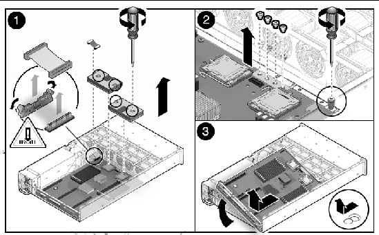
Figure showing how to remove a motherboard(Sun Fire X4250).
|
|
Caution - This procedure requires that you handle components that are sensitive to static discharge. Static discharges can cause component failures. To avoid damage, ensure that you follow antistatic practices as described in Section 2.7, Performing Electrostatic Discharge and Antistatic Prevention Measures. |
See Section 2.4, Powering Off the Server.
2. Attach an antistatic wrist strap.
See Section 2.7, Performing Electrostatic Discharge and Antistatic Prevention Measures.
3. If you are replacing the motherboard only, replace the CPUs, as required.
Apply thermal grease. Follow the applicable grease procedure included with the grease.
See Section 4.7.3, Installing a CPU (Reusing Heatsink).
4. Place the motherboard tray into the chassis. (FIGURE 4-14)
5. Install the 4 screws that secure the motherboard to the bus bar. [3]
Torque screws to 7 inch-pounds (0.8 newton-meters). Use a manual torque driver settable to 7 inch-pounds (0.8 newton-meters) with a No. 2 Phillips screwdriver.
6. Fasten the captive screw at the front of the motherboard. [3]
7. Install the CPU heat sinks on the motherboard assembly.
See Section 4.7.4, Installing a CPU (Replacing Heatsink).
8. Carefully connect the power distribution board ribbon cable to the motherboard. [3]
Make sure it is seated properly.
See Section 5.8.4, Installing a PDB Cable.
9. Connect the two drive data cables.
See Section 1.2.2, System Cables.
|
|
Caution - The drive data cables are delicate. Carefully connect them and make sure that they are seated properly when servicing the motherboard. |
10. Tighten the captive retaining screw that holds the front end of the riser to the motherboard.
Be careful when routing the drive cables so they do not get pinched and are underneath the ribs on the support.
11. Reinstall the PCIe cards and risers.
See Section 4.3.2, Installing a PCIe Riser.
12. Return the server to operation.
See Section 6.1, Installing the Top Cover.
b. Install the server into the rack.
See Section 6.2, Reinstalling the Server in the Rack.
c. Reconnect the power cord (or cords) to the power supply (or supplies).
Verify that the AC Present LED is lit.
See Section 6.4, Powering On the Server.
See Section 6.4, Powering On the Server.
FIGURE 4-14 Installing the Motherboard Assembly
.")
The following topics are covered:
| Note - FRU: This field-replaceable unit should be replaced only by qualified service technicians. Contact your Sun Service representative for assistance. |
A CPU FRU requires trained personnel to apply thermal grease. For Xoption CPUs, the grease is preinstalled.
See Section 1.5, Illustrated Parts Breakdown for illustrations of the server and CPUs.
If you are replacing a faulty CPU, press the Remind button on the motherboard to locate the CPU that you want to replace. (FIGURE 4-15)
The faulty CPU LED flashes when the Fault Remind button is pressed and held. All faulty CPUs are indicated with an amber LED, so that you can install the replacement CPU in the same location.
.")
1. Prepare the server for service.
See Section 2.4, Powering Off the Server.
b. Disconnect the power cord (or cords) from the power supply (or supplies).
See Section 2.4, Powering Off the Server.
c. Slide the server out of the rack.
See Section 2.5, Extending the Server to the Maintenance Position.
d. Attach an antistatic wrist strap.
See Section 2.7, Performing Electrostatic Discharge and Antistatic Prevention Measures.
See Section 2.8, Removing the Top Cover.
2. Identify which CPU to remove. (FIGURE 4-16 [1] )
CPU 0 is closest to the PSU bay. CPU 1 is furthest from the PSU bay.
3. Unscrew the two heatsink screws. (FIGURE 4-16 [2] )
4. Twist the heatsink slightly to break the seal with grease, and then lift off the heatsink.
5. Disengage the lever by rotating upward. (FIGURE 4-16 [3] )
6. Remove the CPU. (FIGURE 4-16 [4] )
.")
To install a CPU do the following. This procedure reuses the existing CPU heatsink.
1. Prepare the server for service.
See Section 2.4, Powering Off the Server.
b. Disconnect the power cord (or cords) from the power supply (or supplies).
See Section 2.4, Powering Off the Server.
c. Slide the server out of the rack.
See Section 2.5, Extending the Server to the Maintenance Position.
d. Attach an antistatic wrist strap.
See Section 2.7, Performing Electrostatic Discharge and Antistatic Prevention Measures.
See Section 2.8, Removing the Top Cover.
2. Remove the heatsink on top of the failed CPU. (FIGURE 4-18 )
4. Clean off the old thermal interface material from the heatsink and CPU, using the supplied alcohol wipe.
6. Place the new CPU in the socket.
Make sure the orientation is correct.
7. Engage the lever by rotating downward and pressing it into the catch. (FIGURE 4-17)
FIGURE 4-17 Installing a CPU (Part 1)
.")
8. Using the supplied grease syringe, empty the syringe on to the CPU in a star shaped pattern.
9. Smooth the grease into a thin even layer on top of the CPU.
You can use a piece of plastic bag over your finger.
10. Orient the heatsink so that the four screws line up with the mounting inserts. (FIGURE 4-18)
11. Tighten the four screws alternately one 1/2 turn in an X pattern until fully seated.
12. Return the server to operation.
See Section 6.1, Installing the Top Cover.
b. Slide the server into the rack.
See Section 6.3, Returning the Server to the Normal Rack Position.
c. Reconnect the power cord (or cords) to the power supply (or supplies).
Verify that the AC Present LED is lit.
See Section 6.4, Powering On the Server.
See Section 6.4, Powering On the Server.
FIGURE 4-18 Installing a CPU (Part 2)
.")
To install a CPU do the following. This procedure replaces the CPU heatsink.
1. Prepare the server for service.
See Section 2.4, Powering Off the Server.
b. Disconnect the power cord (or cords) from the power supply (or supplies).
See Section 2.4, Powering Off the Server.
c. Slide the server out of the rack.
See Section 2.5, Extending the Server to the Maintenance Position.
d. Attach an antistatic wrist strap.
See Section 2.7, Performing Electrostatic Discharge and Antistatic Prevention Measures.
See Section 2.8, Removing the Top Cover.
2. Remove the shipping cover from socket.
3. Clean the top of the CPU with the provided alcohol wipe.
4. Place the CPU in the socket with the correct orientation.
5. Engage the lever by rotating downward and pressing into the catch.
6. Remove the plastic protective cover from the heatsink.
Be careful not to disturb or touch the pre-installed thermal interface material.
7. Orient the heatsink so the four screws line up with the mounting studs.
8. Tighten the four screws alternately one 1/2 turn in an X pattern until fully seated.
9. Return the server to operation.
See Section 6.1, Installing the Top Cover.
b. Slide the server into the rack.
See Section 6.3, Returning the Server to the Normal Rack Position.
c. Reconnect the power cord (or cords) to the power supply (or supplies).
Verify that the AC Present LED is lit.
See Section 6.4, Powering On the Server.
See Section 6.4, Powering On the Server.
The following topics are covered:
Clearing CMOS settings resets the BIOS settings, including the BIOS password. You can reset a password from the BIOS screen or with a jumper. You can also clear the CMOS NVRAM and BIOS password by changing jumpers as listed in TABLE 4-1.
To reset a password for the Service Processor, access the BIOS Security screen.
2. Press F2 at the Sun splash screen to enter Setup.
3. At the BIOS screen, move to the Security Screen tab.
See Section , BIOS Screens for additional BIOS information.
To reset a password for the BIOS by changing a jumper.
1. Prepare the server for service.
See Section 2.4, Powering Off the Server.
b. Disconnect the power cord (or cords) from the power supply (or supplies).
See Section 2.4, Powering Off the Server.
c. Slide the server out of the rack.
See Section 2.5, Extending the Server to the Maintenance Position.
d. Attach an antistatic wrist strap.
See Section 2.7, Performing Electrostatic Discharge and Antistatic Prevention Measures.
See Section 2.8, Removing the Top Cover.
2. Locate the 2 pin header J602.
Access the J602 jumper on the rear of the motherboard next to the SP, below PCIe slot 1, PCIe riser 1.
3. Place the jumper across the 2 pins of the header..
4. Power on the server and boot until you see a message that the password has been cleared.
5. Power off the server, and remove AC power.
6. Remove the jumper from J602.
7. Return the server to operation.
See Section 6.1, Installing the Top Cover.
b. Slide the server into the the rack.
See Section 6.3, Returning the Server to the Normal Rack Position.
c. Reconnect the power cord (or cords) to the power supply (or supplies).
Verify that the AC Present LED is lit.
See Section 6.4, Powering On the Server.
See Section 6.4, Powering On the Server.
To clear the NVRAM using a jumper:
1. Prepare the server for service.
See Section 2.4, Powering Off the Server.
b. Disconnect the power cord (or cords) from the power supply (or supplies).
See Section 2.4, Powering Off the Server.
c. Slide the server out of the rack.
See Section 2.5, Extending the Server to the Maintenance Position.
d. Attach an antistatic wrist strap.
See Section 2.7, Performing Electrostatic Discharge and Antistatic Prevention Measures.
See Section 2.8, Removing the Top Cover.
2. Locate the jumper header J1802.
Access the J1802 jumper on the rear of the motherboard next to the SATA connector , below PCIe slot 0, PCIe riser 0.
3. Place the jumper across the 2 pins of the header.
4. Power on the server and boot until the message about NVRAM has been cleared.
5. Power off the server, and remove AC power cables.
See Section 2.4, Powering Off the Server.
6. Remove the jumper from J1802.
7. Return the server to operation.
See Section 6.1, Installing the Top Cover.
b. Slide the server into the the rack.
See Section 6.3, Returning the Server to the Normal Rack Position.
c. Reconnect the power cord (or cords) to the power supply (or supplies).
Verify that the AC Present LED is lit.
See Section 6.4, Powering On the Server.
See Section 6.4, Powering On the Server.
If the SP (service processor) software becomes corrupted, you can reinstall the default SP software image from the Tools and Drivers CD.
To reinstall the default SP software image:
1. Copy the following SP files from the Tools and Drivers CD, located in the BMCrecovery directory, to a USB flash device.
| Note - SOCFLASH.EXE is a DOS-based SP firmware recovery tool that offers customers an alternate method to using ipmiflash for flash recovery. |
2. Remove AC power from the server to be flashed.
See Section 2.4, Powering Off the Server.
|
|
Caution - Do not attempt to flash the system while it is still powered on. An unrecoverable error might occur. |
3. Disconnect the power cord (or cords) from the power supply (or supplies).
See Section 2.4, Powering Off the Server.
4. Extend the server into the maintenance position.
See Section 2.5, Extending the Server to the Maintenance Position.
See Section 2.8, Removing the Top Cover.
6. Remove PCI cards from riser 1.
See Section 4.4.2, Removing PCIe Cards.
7. Use a jumper cap to short the pins at jumper J16 on the server motherboard.
JP16 is located toward the rear of the board, between riser 1 and riser 2 and below PCIe slot 1, PCIe riser 1.
8. Insert a bootable flash drive into a USB port.

See Section 6.4, Powering On the Server.
See Section 6.4, Powering On the Server.
A message appears stating that the BMC was not found.
The server takes up to three minutes to boot.
11. Press F2 to enter the system BIOS and verify that the flash device is in the boot order.
12. After the flash device has booted, run the following command:
socflash.exe SP binary backup file
socflash.exe s92v092.bin backup.bin
13. After a successful flash, remove the AC power.
See Section 2.4, Powering Off the Server.
15. Remove the flash drive from the USB port.
16. Replace PCI cards from riser 1.
See Section 4.4.3, Installing PCIe Cards.
17. Return the server to operation.
See Section 6.1, Installing the Top Cover.
b. Slide the server into the the rack.
See Section 6.3, Returning the Server to the Normal Rack Position.
c. Reconnect the power cord (or cords) to the power supply (or supplies).
Verify that the AC Present LED is lit.
See Section 6.4, Powering On the Server.
See Section 6.4, Powering On the Server.
18. Press F2 to start the BIOS.
19. Confirm that the SP is listed in the BIOS settings under Server/AST2000 LAN Configuration.
20. Exit the BIOS and start the operating system.
|
|
Caution - Do not use the Reset and NMI Dump switches unless you are instructed to do so by a Field Service engineer. |
The Reset switch on the motherboard sends a reset order to the CPUs, resetting the main system, but not the service processor. The button for this switch is one of the 3 hidden (recessed) buttons on the back of the motherboard located between the NET MGT and NET0 connectors and closest to NET0. It can be pushed by sticking a paper clip or similar object through the hole provided on the rear of the chassis.
The NMI button is the center button of the row of 3 hidden (recessed) buttons on the back of the motherboard located between the NET MGT and NET0 connectors. The button for this switch can be pushed by sticking a paper clip or similar object through the hole provided on the rear of the chassis.
The Non-Maskable Interrupt (NMI) Dump switch sends an NMI order to the CPUs, which is used by Field Service for debugging activities at the request of operating system engineers. NMI can also be asserted by ILOM. Refer to the Sun Integrated Lights Out Manager 2.0 User's Guide.
| Sun Fire X4250 Server Service Manual | 820-4214-11 |
Copyright © 2009 Sun Microsystems, Inc. All rights reserved.