Troubleshooting DIMM Problems
|
This chapter describes how to detect and correct problems with the server’s Dual Inline Memory Modules (DIMM)s. It includes the following sections:
DIMM Population Rules
The DIMM population rules for the server are as follows:
- Each CPU can support a maximum of eight DIMMs.
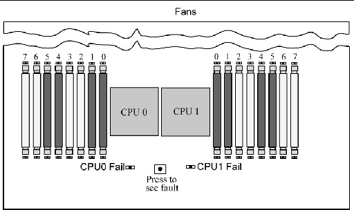
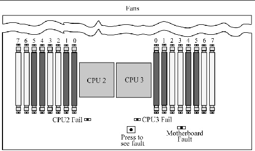
- The DIMM slots are paired and the DIMMs must be installed in pairs (0-1, 2-3, 4-5, and 6-7). See FIGURE 3-1 and FIGURE 3-2. The memory sockets are colored black or white to indicate which slots are paired by matching colors.
- DIMMs are populated starting from the outside (away from the CPU) and working toward the inside.
- CPUs with only a single pair of DIMMs must have those DIMMs installed in that CPU’s outside white DIMM slots (6 and 7). See FIGURE 3-1 and FIGURE 3-2.
- Only DDR2 800 Mhz, 667Mhz, and 533Mhz DIMMs are supported.
- Each pair of DIMMs must be identical (same manufacturer, size, and speed).
DIMM Replacement Policy
Replace a DIMM when one of the following events takes place:
- The DIMM fails memory testing under BIOS due to Uncorrectable Memory Errors (UCEs).
- UCEs occur and investigation shows that the errors originated from memory.
In addition, a DIMM should be replaced whenever more than 24 Correctable Errors (CEs) originate in 24 hours from a single DIMM and no other DIMM is showing further CEs.
- If more than one DIMM has experienced multiple CEs, other possible causes of CEs have to be ruled out by a qualified Sun Support specialist before replacing any DIMMs.
Retain copies of the logs showing the memory errors per the above rules to send to Sun for verification prior to calling Sun.
How DIMM Errors Are Handled by the System
This section describes system behavior for the two types of DIMM errors: UCEs and CEs, and also describes BIOS DIMM error messages.
Uncorrectable DIMM Errors
For all operating systems (OS’s), the behavior is the same for UCEs:
1. When an UCE occurs, the memory controller causes an immediate reboot of the system.
2. During reboot, the BIOS checks the Machine Check registers and determines that the previous reboot was due to an UCE, then reports this in POST after the memtest stage:
A Hypertransport Sync Flood occurred on last boot
3. BIOS reports this event in the service processor’s system event log (SEL) as shown in the sample IPMItool output below:
# ipmitool -H 10.6.77.249 -U root -P changeme -I lanplus sel list
8 | 09/25/2007 | 03:22:03 | System Boot Initiated #0x02 | Initiated by warm 	      reset | Asserted
9 | 09/25/2007 | 03:22:03 | Processor #0x04 | Presence detected | Asserted
a | 09/25/2007 | 03:22:03 | OEM #0x12 |  | Asserted
b | 09/25/2007 | 03:22:03 | System Event #0x12 | Undetermined system hardware      failure | Asserted
c | OEM record e0 | 00000002000000000029000002
d | OEM record e0 | 00000004000000000000b00006
e | OEM record e0 | 00000048000000000011110322
f | OEM record e0 | 00000058000000000000030000
10 | OEM record e0 | 000100440000000000fefff000
11 | OEM record e0 | 00010048000000000000ff3efa
12 | OEM record e0 | 10ab0000000010000006040012
13 | OEM record e0 | 10ab0000001111002011110020
14 | OEM record e0 | 0018304c00f200002000020c0f
15 | OEM record e0 | 0019304c00f200004000020c0f
16 | OEM record e0 | 001a304c00f45aa10015080a13
17 | OEM record e0 | 001a3054000000000320004880
18 | OEM record e0 | 001b304c00f200001000020c0f
19 | OEM record e0 | 80000002000000000029000002
1a | OEM record e0 | 80000004000000000000b00006
1b | OEM record e0 | 80000048000000000011110322
1c | OEM record e0 | 80000058000000000000030000
1d | OEM record e0 | 800100440000000000fefff000
1e | OEM record e0 | 80010048000000000000ff3efa
1f | 09/25/2007 | 03:22:06 | System Boot Initiated #0x03 | Initiated by warm      reset | Asserted
20 | 09/25/2007 | 03:22:06 | Processor #0x04 | Presence detected | Asserted
21 | 09/25/2007 | 03:22:15 | System Firmware Progress #0x01 | Memory      initialization | Asserted
22 | 09/25/2007 | 03:22:16 | Memory | Uncorrectable ECC | Asserted | CPU 2 DIMM 0
23 | 09/25/2007 | 03:22:16 | Memory | Uncorrectable ECC | Asserted | CPU 2 DIMM 1
24 | 09/25/2007 | 03:22:16 | Memory | Memory Device Disabled | Asserted | CPU      2 DIMM 0
25 | 09/25/2007 | 03:22:16 | Memory | Memory Device Disabled | Asserted | CPU      2 DIMM 1
|
The lines in the display start with event numbers (in hex), followed by a description of the event. TABLE 3-1 describes the contents of the display:
TABLE 3-1 Lines in IPMI Output
|
Event (hex)
|
Description
|
|
8
|
UCE caused a Hypertransport sync flood which lead to system's warm reset. #0x02 refers to a reboot count maintained since the last AC power reset.
|
|
9
|
BIOS detected and initiated 4 processors in system.
|
|
a
|
BIOS detected a Sync Flood caused this reboot.
|
|
b
|
BIOS detected a hardware error caused the Sync Flood.
|
|
c to 1e
|
BIOS retrieved and reported some hardware evidence, including all processors' Machine Check Error registers (events 14 to 18).
|
|
1f
|
After BIOS detected that a UCE had occurred, it located the DIMM and reset. 0x03 refers to reboot count.
|
|
21 to 25
|
BIOS off-lined faulty DIMMs from system memory space and reported them. Each DIMM of a pair is being reported, since hardware UCE evidence cannot lead BIOS any further than detection of a faulty pair.
|
Correctable DIMM Errors
If a DIMM has 24 or more correctable errors in 24 hours, it is considered defective and should be replaced.
At this time, CEs are not logged in the server’s system event logs. They are reported or handled in the supported OS’s as follows:
a. A Machine Check error-message bubble appears on the task bar.
b. The user must manually open Event Viewer to view errors. Access Event Viewer through this menu path:
Start-->Administration Tools-->Event Viewer
c. The user can then view individual errors (by time) to see details of the error.
Solaris FMA reports and (sometimes) retires memory with correctable Error Correction Code (ECC) errors. See your Solaris Operating System documentation for details. Use the command:
fmdump -eV
to view ECC errors
The HERD utility can be used to manage DIMM errors in Linux. See the x64 Servers Utilities Reference Manual for details.
- If HERD is installed, it copies messages from /dev/mcelog to /var/log/messages.
- If HERD is not installed, a program called mcelog copies messages from /dev/mcelog to /var/log/mcelog.
The Bootable Diagnostics CD described in Chapter 2 also captures and logs CEs.
BIOS DIMM Error Messages
The BIOS displays and logs the following DIMM error messages:
NODE-n Memory Configuration Mismatch
The following conditions will cause this error message:
- The DIMMs mode is not paired (running in 64-bit mode instead of 128-bit mode).
- The DIMMs’ speed is not same.
- The DIMMs do not support ECC.
- The DIMMs are not registered.
- The MCT stopped due to errors in the DIMM.
- The DIMM module type (buffer) is mismatched.
- The DIMM generation (I or II) is mismatched.
- The DIMM CL/T is mismatched.
- The banks on a two-sided DIMM are mismatched.
- The DIMM organization is mismatched (128-bit).
- The SPD is missing Trc or Trfc information.
DIMM Fault LEDs
When you press the Press to See Fault button on the motherboard or the mezzanine board, LEDs next to the DIMMs flash to indicate that the system has detected 24 or more CEs in a 24-hour period on that DIMM.
| Note - The DIMM Fault and Motherboard Fault LEDs operate on stored power for up to a minute when the system is powered down, even after the AC power is disconnected, and the motherboard (or mezzanine board) is out of the system. The stored power lasts for about half an hour.
|
| Note - Disconnecting the AC power removes the fault indication. To recover fault information look in the SP SEL, as described in the Sun Integrated Lights Out Manager 2.0 User's Guide.
|
- DIMM fault LED is off - The DIMM is operating properly.
- DIMM fault LED is flashing (amber) - At least one of the DIMMs in this DIMM pair has reported 24 CEs within a 24-hour period.
- Motherboard Fault LED on mezzanine is on - There is a fault on the motherboard. This LED is there because you cannot see the motherboard LEDs when the mezzanine board is present.
| Note - The Motherboard Fault LED operates independently of the Press to See Fault button, and does not operate on stored power.
|
See FIGURE 3-1 for the locations of DIMMs and LEDs on the motherboard. See FIGURE 3-2 for the locations of DIMMs and LEDs on the mezzanine board.
FIGURE 3-1 DIMMs and LEDs on Motherboard

FIGURE 3-2 DIMMs and LEDs on Mezzanine Board

Isolating and Correcting DIMM ECC Errors
If your log files report an ECC error or a problem with a DIMM, complete the steps below until you can isolate the fault.
In this example, the log file reports an error with the DIMM in CPU0, slot 7. The fault LEDs on CPU0, slots 6 and 7 are on.
To isolate and correct DIMM ECC errors:
1. If you have not already done so, shut down your server to standby power mode and remove the cover.
2. Inspect the installed DIMMs to ensure that they comply with the DIMM Population Rules.
3. Press the PRESS TO SEE FAULT button, and inspect the DIMM fault LEDs. See FIGURE 3-1 and FIGURE 3-2.
A flashing LED identifies a component with a fault.
- For CEs, the LEDs correctly identify the DIMM where the errors were detected.
- For UCEs, both LEDs in the pair flash if there is a problem with either DIMM in the pair.
| Note - If your server is equipped with a mezzanine board, the motherboard DIMMs and LEDs will be hidden beneath it. However, the Motherboard Fault LED lights to indicate that there is a problem on the motherboard (only while AC power is still connected). If the Motherboard Fault LED on the mezzanine board lights, remove the mezzanine board as described in your server’s service manual, and inspect the LEDs on the motherboard.
|
4. Disconnect the AC power cords from the server.

|
Caution - Before handling components, attach an ESD wrist strap to a chassis ground (any unpainted metal surface). The system’s printed circuit boards and hard disk drives contain components that are extremely sensitive to static electricity.
|
| Note - To recover fault information look in the SP SEL, as described in the Sun Integrated Lights Out Manager 2.0 User's Guide.
|
5. Remove the DIMMs from the DIMM slots in the CPU.
Refer to your server’s service manual for details.
6. Visually inspect the DIMMs for physical damage, dust, or any other contamination on the connector or circuits.
7. Visually inspect the DIMM slot for physical damage. Look for cracked or broken plastic on the slot.
8. Dust off the DIMMs, clean the contacts, and reseat them.

|
Caution - Use only compressed air to dust DIMMs.
|
9. If there is no obvious damage, replace any failed DIMMs.
For UCEs, if the LEDs indicate a fault with the pair, replace both DIMMs. Ensure that they are inserted correctly with ejector latches secured.
10. Reconnect AC power cords to the server.
11. Power on the server and run the diagnostics test again.
12. Review the log file.
If the tests identify the same error, the problem is in the CPU, not the DIMMs.
| Sun Fire X4140, X4240, and X4440 Servers Diagnostics Guide
|
820-3067-14
|
   
|
Copyright © 2010, Oracle and/or its affiliates. All rights reserved.


