This appendix contains information about the locations and behaviors of the status and fault LEDs on the server. The information is organized to describe external LEDs that can be viewed on the outside of the server, and internal LEDs that can be viewed only with the main cover removed.
This appendix contains the following sections:
C.1 Front Panel LEDs
EXAMPLE C-1 Close Up of Controls and Indicators
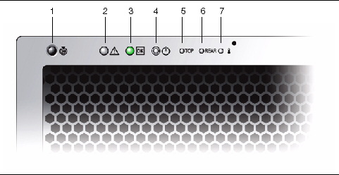
TABLE C-2 lists and describes the controls and indicators LEDs.
TABLE C-1 Controls and Indicators
|
#
|
Name
|
Color
|
Description
|
|
|
1
|
Locate button/LED
|
White
|
Press to toggle on/off locally. Remains on (as fast blinking 4Hz) for 30 minutes or until turned off.
Operators can turn this LED on remotely to help them locate the server in a crowded server room:
- In the ILOM GUI, navigate to System Monitoring > Indicators and select the radio button next to /SYS/LOCATE. From the Actions drop-down menu, select “Set LED to Fast Blink” or “Turn LED Off.”
- In the CLI, enter:
set /SYS/LOCATE value=[fast_blink|off]
- Press to turn on or off.
Press the Locate LED/Switch for five seconds to turn all indicators on for 15 seconds.
|

|
|
2
|
System Fault LED
|
Amber
|
Off--Normal operation
On--Service action is required.
A system running under these conditions are in a fault condition, but the SP does not log the reason the service LED is illuminated:
- 220VAC with only 1 PSU
- 110VAC with only two PSUs
|

|
|
3
|
Power/OK LED
|
Green
|
Steady on--Power is on and system is operational.
Blinking--Standby power is on but main power is off. Blinks briefly once every 3 seconds.
Off--Power is off.
|

|
|
4
|
System power button
|
|
If on, press briefly for a controlled shut down. Press and hold for 4 seconds for immediate shutdown.

Caution - Caution there may be data loss for immediate shutdown.
See Section 2.1, Powering On the Server for details.
|
|
|
5
|
Top fault LED
|
Amber
|
On--Drive or fan fault: open top cover to service.
|

|
|
6
|
Rear fault LED
|
Amber
|
On--Power supply or system controller fault (service is required at rear of system).
|

|
|
7
|
System Over Temperature
|
Amber
|
On--Server is in over-temperature condition.
|

|
C.1.1 Rear Panel LEDs
FIGURE C-1 Sun Fire X4500 Server Rear Panel
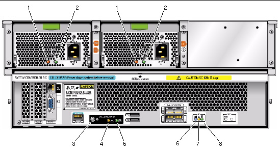
FIGURE C-2 Sun Fire X4540 Server Rear Panel
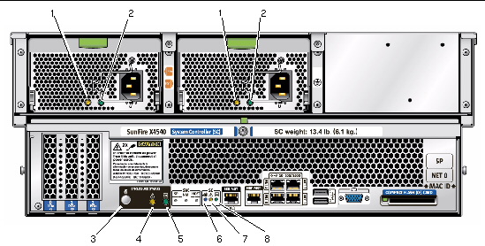
TABLE C-2 Sun Fire X4540 External LEDs
|
#
|
Name
|
Color
|
Function
|
|
1
|
Power Supply LED
|
Amber
|
Steady on--Fault. Service action required.
|
|
2
|
OK
|
Green
|
Steady on--Power is on (AC/DC are OK).
Blinking --Blinks briefly once every 3 seconds. Standby power is on (AC is OK).
Off -- Power is off.
|
|
3
|
Locate button/LED
|
White
|
Toggles on/off locally--Operators can turn on this on remotely to help them locate the enclosure in a crowded server room. Press to turn off.
|
|
4
|
System Fault LED
|
Amber
|
Off--Normal operation
On--Service action is required.
A system running under these conditions are in a fault condition, but the SP does not log the reason the service LED is illuminated:
- 220VAC with only 1 PSU
- 110VAC with only two PSUs
|
|
5
|
System Power LED
|
Green
|
Steady on-- Power is on and system is operational.
Blinking--Standby power is on but main power is off. Blinks briefly once every 3 seconds.
Off -- Power is off.
|
|
6
|
Ready to Remove
|
Blue
|
Ready to remove (service action allowed)
|
|
7
|
Fault
|
Amber
|
Fault (Service action required)
|
|
8
|
OK
|
Green
|
OK (no action required)
|
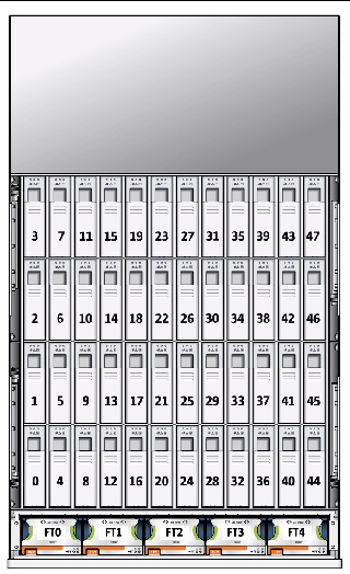
C.2 Disk Drive and Fan Tray LEDs
FIGURE C-3 shows the location of the internal LEDs. FIGURE C-5 shows a close-up view of the disk drive and fan trays, including the symbols that identify the LEDs.
| Note - On fan trays, the green and amber (OK and Fault) LEDs might be on simultaneously. This indicates that while a fan has failed, at least one of its fans is still operational.
|
| Note - Early fan trays had a blue LED that was not activated. Later versions of the fan trays have only a green and amber LED.
|
FIGURE C-3 Disk Drive and Fan Trays (X4500)

Figure Legend
|
0
|
Boot drive
|
|
1
|
Boot drive
|
FIGURE C-4 Disk Drive and Fan Trays (X4540)
 [ D ]
[ D ]
Figure Legend
|
1
|
Boot drive
|
|
2
|
Boot drive
|
|
3
|
Boot drive
|
|
4
|
Boot drive
|
FIGURE C-5 Disk Drive and Fan Tray LEDs
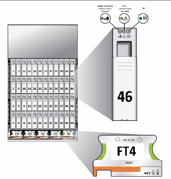
Diagram showing the locations of the disk drive and fan tray LEDs.
TABLE C-3 lists the disk drive LEDs:
TABLE C-3 Internal LEDs
|
Name
|
Color
|
Function
|
|
Disk Drives
|
|
Status (Power)
|
Green
|
Unit is OK. See Note in Section C.2, Disk Drive and Fan Tray LEDs.
|
|
Fault (Alert)
|
Amber
|
Service action is required.
|
|
Ready to Remove
|
Blue
|
Service action is allowed.
|
|
Fan Trays
|
|
Status
|
Green
|
Unit is OK. Blinking = data transfer.
|
|
Fault
|
Amber
|
Fault (Service action required)
|
C.2.1 CPU Board LEDs
The CPU board has three types of LEDs. They are listed in TABLE C-3 and appear in FIGURE C-6.
The CPU LEDs are active only when the Remind button is depressed. They blink to indicate a failure; otherwise they stay Off.
| Note - The CPU and DIMM LEDs continue to indicate a failure until the system is powered on. The Battery LED continues to indicate a failure until the service processor is started.
|
FIGURE C-6 CPU Board, Including LEDs and Remind Switch (X4500)

Figure Legend
|
1
|
Back of system
|
|
2
|
DIMM fault LEDs under DIMM eject levers
|
|
3
|
CPU 1 fault LED
|
|
4
|
CPU 0 fault LED
|
|
5
|
Battery fault LED
|
|
6
|
Remind button (LEDs are active only when the Remind button is pressed.)
|
|
7
|
DIMM fault LED (under DIMM eject levers)
|
|
8
|
Front of system
|
FIGURE C-7 CPU Board, Including LEDs and Remind Switch (Sun Fire X4540)
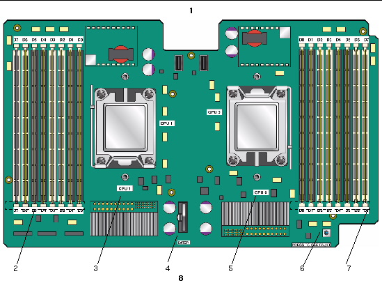
Diagram showing the locations of the disk drive and fan tray LEDs.
Figure Legend
|
1
|
Back of system
|
|
2
|
DIMM fault LEDs under DIMM eject levers (7, 6, 5, 4, 3, 2, 2, 1, 0)
|
|
3
|
CPU 1 fault LED
|
|
4
|
Battery fault LED
|
|
5
|
CPU 0 fault LED
|
|
6
|
Remind button (LEDs are active only when the Remind button is pressed.)
|
|
7
|
DIMM fault LEDs under DIMM eject levers (0, 1, 2, 3, 4, 5, 6, 7)
|
|
8
|
Front of system
|
TABLE C-3 lists the CPU Board LEDs:
TABLE C-4 Internal LEDs
|
Name
|
Color
|
Function
|
|
DIMM Failure
|
Amber
|
Blinks to indicate that the system has found a fault with the DIMM. Restart system to clear fault.
|
|
CPU Failure
|
Amber
|
Blinks to indicate that the system has found a fault with a CPU. Restart system to clear fault.
|
|
Battery Failure
|
Amber
|
Blinks to indicate that the system has found a fault with the battery. Start service processor to clear fault.
|
C.3 GRASP Board LED (Sun Fire X4500)
The GRASP board has one fault LED:
- LED is off: Standby power is not reaching the GRASP board.
- LED is lit (green): 3.3V standby power is reaching the GRASP board.
TABLE C-3 lists the CPU LEDs:
TABLE C-5 Internal LEDs
|
Name
|
Color
|
Function
|
|
DIMM Failure
|
Amber
|
Blinks to indicate that the system has found a fault with the DIMM. Restart system to clear fault.
|
|
CPU Failure
|
Amber
|
Blinks to indicate that the system has found a fault with a CPU. Restart system to clear fault.
|
|
Battery Failure
|
Amber
|
Blinks to indicate that the system has found a fault with the battery. Start service processor to clear fault.
|
The GRASP board (service processor) is located in the PCI-X slot nearest the CPU. See FIGURE C-8 for location details.
FIGURE C-8 GRASP Board Location (X4500)

C.4 CPU Module Debug LEDs
The X4500 board is shown.
FIGURE C-9 CPU Module Debug LEDs
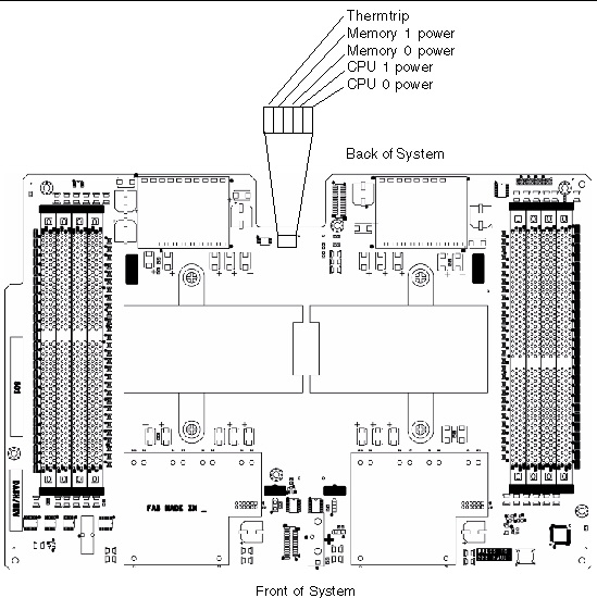
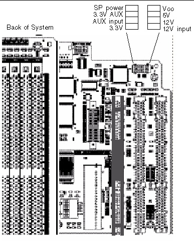
FIGURE C-10 I/O Controller Board Debug LEDs
| Sun Fire X4500/X4540 Server Service Manual
|
819-4359-19
|
   
|
Copyright © 2010, Oracle and/or its affiliates. All rights reserved.