Power Reset and Initialization Sequences
|
This appendix describes the power-on and power-off reset sequences.
E.1 Power-On Reset Sequence
The power-on sequence is initiated as soon as power is applied or when the power button is pushed, depending on the BIOS settings.
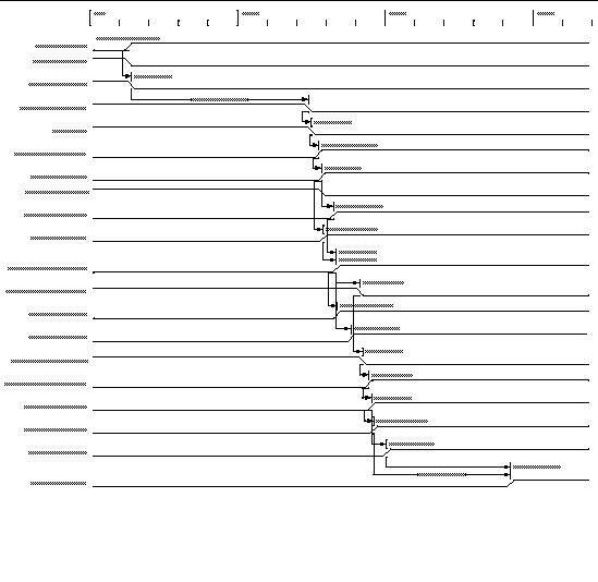
When the sequence is initiated, the main power supplies are enabled, then the hot-swap circuit for the main 12V rail is enabled. When 12V is up, the supplies are sequenced as follows:
- 1.5V, 3.3V, and -12V
- 1.8V, 2.5V, and 1.25V
- Processor core voltage
- 1.2V and 1.5V
When all of the rails are within 5%, the voltage monitor chip waits for 210 mS then asserts ALL_POWERGOOD, which starts the boot sequence.
The diagram in FIGURE E-1 shows the power-on sequence. TABLE E-1 defines the symbols used in the diagram and describes the power-on sequence timing parameters.
FIGURE E-1 Power-On Sequence

TABLE E-1 Parameters From Power-On Sequence
|
Parameter
|
Description
|
Value
|
Units
|
|
t_NEXT_RAIL
|
Delay from one rail, Power Good to next rail, Enable
|
1
|
mS
|
|
t_PSON_ON_DELAY
|
Soft-start delay for LTC3733
|
300
|
mS
|
|
t_HOTSWAP_GOOD
|
Delay from Hotswap Enable to Hotswap Good
|
12.4
|
mS
|
|
t_ATH26_DELAY
|
ATH26 Module Turn-on time + Power Good delay
|
20
|
mS
|
|
t_SIL20C2_DELAY
|
SIL20C2 Module Turn-on time + Power Good delay
|
3
|
mS
|
|
t_DDR_DELAY
|
DDR Module Turn-on time + Power Good delay
|
40
|
mS
|
|
t_LTC3025_DELAY
|
LTC3025 Turn-on time + Power Good delay
|
1
|
mS
|
|
t_IPM12_DELAY
|
IPM12 Module Turn-on time + Power Good delay
|
25
|
mS
|
|
t_VRM_DELAY
|
SIL06 Module Turn-on time + Power Good delay
|
10
|
mS
|
|
t_RESET_DELAY
|
LTC2902 delay from voltage in spec to release of reset line
|
210
|
mS
|
E.2 Power-Off Sequence
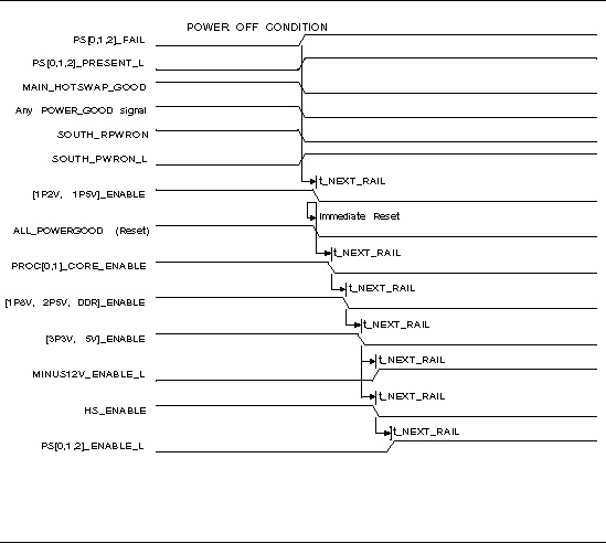
A power-off sequence is initiated by a request from the SP board management controller, an OS-level shutdown, a power button press, or a fault condition.
A power supply fault (main or voltage converter) or a thermal event (THERMTRIP) can trigger a hardware-level shutdown.
FIGURE E-2 shows the power-off sequence. TABLE E-2 defines the symbols used in the diagram and describes the power-off sequence timing parameters.
FIGURE E-2 Power-Off Sequence

TABLE E-2 Power-Off Sequence Timing Parameters
|
Symbol
|
Parameter
|
Value (in ms)
|
|
t_NEXT_RAIL
(fault condition)
|
Delay from one rail Enable deassertion to next rail Enable deassertion after a fault condition.
|
1 ms
|
|
t_ NEXT_RAIL
(normal power-down)
|
Delay from one rail Enable deassertion to next rail Enable deassertion after a power-down initiated by the Host/SP.
|
20 ms
|
| Sun Fire X4500/X4540 Server Service Manual
|
819-4359-19
|
   
|
Copyright © 2010, Oracle and/or its affiliates. All rights reserved.

