| C H A P T E R 1 |
|
Installing and Using Your Sun X4500-J Slide Rails |
This document describes how to install and use the Sun X4500-J slide rails to mount your Sun Fire X4500 and X4540 storage servers, Sun Storage 7210 Unified Storage System, and Sun Storage J4500 Array into a compatible rack system.
This document includes the following sections:
The Sun X4500-J Slide Rails are designed for use with Sun 4RU (Rack Unit), 48 HDD storage products, such as the Sun Fire X4500 and X4540 storage servers; Sun Storage 7210 Unified Storage System; and Sun Storage J4500 Array. After unpacking your system, follow the instructions described in this section to install the slide rails and mount your system into a compatible rack.
Once the system is racked, use the installation documentation included with the system to complete its setup.
At least three people are needed to install the system into the rack:
| Note - This assumes that a mechanical lift is used. If a mechanical lift is not available, you must depopulate the system of some of its components to reduce the weight. |
Sun recommends using the Sun Rack 1000-42 and Sun Rack 1000-38, or Sun Rack II 1042/E and Sun Rack II 1242/E products with your Sun X4500-J slide rails. However, the slide rails are compatible with a wide range of equipment racks that meet the following standards:
The slide rail assemblies are shipped assembled. The assemblies include the following parts:
Before you start this procedure, unpack the slide rail assemblies from the packing box and place them on a flat surface. You must remove the inner rail (as explained in this procedure) before trying to mount it to the system chassis.
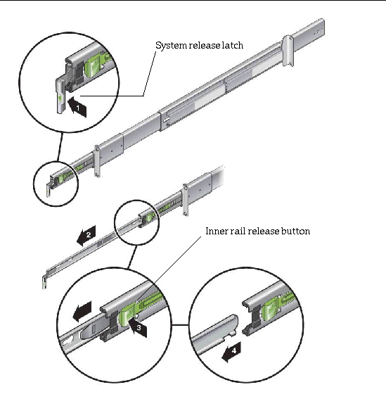
1. Push the system release latch and slide out the inner rail to its fully extended position (until it reaches the internal stops). See the inset arrows labeled 1 and 2 in FIGURE 1-1.
2. Push the green inner rail release button (with embossed arrow), and remove the inner rail from the slide rail assembly. See the inset arrows labeled 3 and 4 in FIGURE 1-1.
FIGURE 1-1 Disassembling the Slide Rail Assembly Before Installation
3. Repeat steps 1 and 2 for the remaining slide rail assembly.
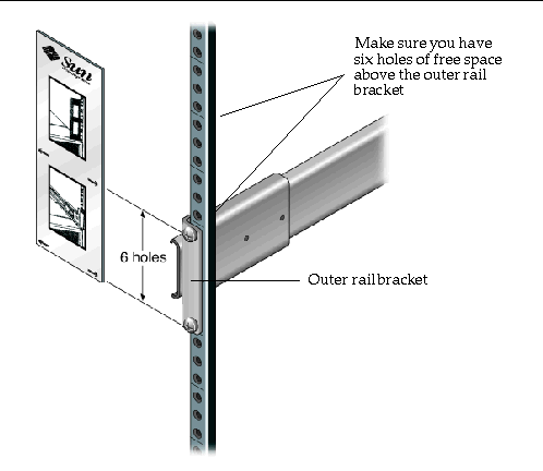
1. Determine where in the rack you want to install the system.
The Sun X4500-J slide rails are designed for Sun 4RU 48 HDD storage products. A paper rack-mount template is shipped with the slide-rail assembly.
2. Set the rack-mount template above the bottom system mounted in your rack.
3. Prepare to install the outer rail/middle rail at the location indicated by the arrows on the rack-mount template.
In a rack with three holes per rack unit, these systems occupy 12 holes in height. See FIGURE 1-2.
FIGURE 1-2 Determining Where to Attach the Outer Rail/Inner Rail
Have the following available before you begin the assembly:
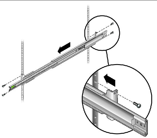
1. Make sure the slide-rail assembly is adjusted lengthwise to facilitate mounting to the front and rear posts of your rack. See FIGURE 1-3.
2. Insert and hand-tighten the bottom screws first to hold each slide rail in place.
The screws should be hand-tightened now because you will use a slide rail spacing tool (called the Rack Installation Aid) later to make final adjustments.
3. Insert and hand-tighten the rest of the screws in the rail assembly front and rear mounting-bracket holes.
FIGURE 1-3 Attaching the Outer Rail/Inner Rail
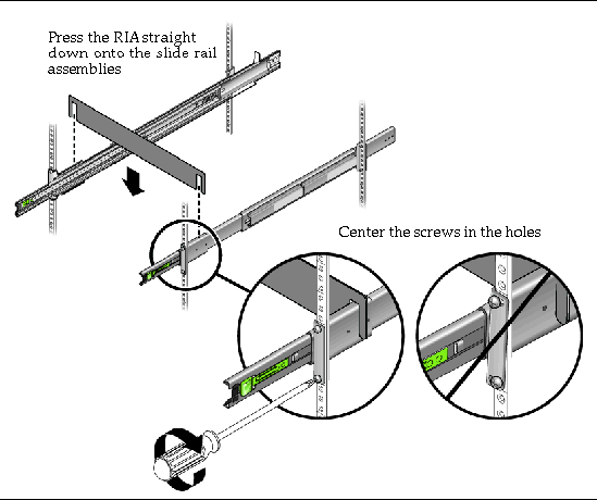
The Rack Installation Aid (RIA) is used to help with the critical alignment and spacing of the rails to ensure an even fit and prevent tilted alignment.
1. Once both slide rail assemblies are loosely fastened at the front and rear, place the RIA spacing tool over both slide-rail assemblies at the front of the rack. See FIGURE 1-4.
The RIA spacing tool should have a snug fit and might require pressure to ensure that it is fully engaged with the left and right slide-rail assemblies.
2. Center the bracket holes with the appropriate holes in the rack, and tighten all four screws on left and right front mounting brackets with a #2 Phillips screwdriver. See FIGURE 1-4.
FIGURE 1-4 Using the Rack Installation Aid (RIA) Spacing Tool at the Front of the Rack
3. Remove the RIA slide-rail spacing tool with care, as follows (removing the tool unevenly can deform its alignment flanges):
4. Take the RIA spacing tool and proceed to the rear of the rack.
5. Place the RIA spacing tool over the slide-rail assembly at the rear of the rack, between the rail stiffeners. See FIGURE 1-5.
The spacing tool should have a snug fit and might require pressure to ensure that it is fully engaged with the left and right slide-rail assemblies. See FIGURE 1-6.
FIGURE 1-5 Using the Rack Installation Aid (RIA) Spacing Tool at the Rear of the Rack
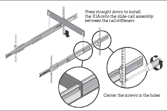
6. Center the bracket holes with the appropriate holes in the rack, and tighten all four screws on the left and right rear mounting brackets with a #2 Phillips screwdriver. See FIGURE 1-5 and FIGURE 1-6.
FIGURE 1-6 Tighten Screws on the Right Rear Mounting Bracket
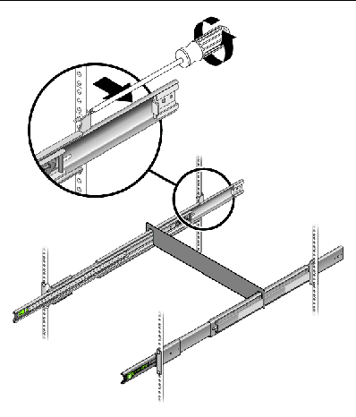
7. Carefully, remove the RIA slide rail spacing tool from the rails by lifting both ends of the tool straight up at the same time.
The inner rails must be installed on to the system chassis before installing the system into the rack.
1. Pick up one of the inner rails and orient it so that the system release latch is toward the front of the system.
2. Position the inner rail on the chassis by aligning the six-keyed openings on the inner rail with the six mounting pins on the side of the chassis. See FIGURE 1-7.
FIGURE 1-7 Attaching the Inner Rail to the Chassis
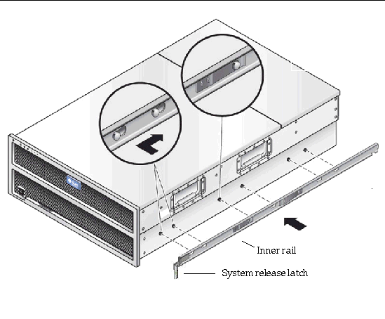
3. While pressing the front and rear part of the rail against the chassis, slide the rail toward the rear of the chassis until the pin retaining clip locks into place with an audible click. See the inset with the arrow in FIGURE 1-7.
4. Verify that all six mounting pins are properly engaged with the keyed slide-rail pin slots.
If the rail does not fit flush against the chassis, reinstall it as described in How to Remove the Inner Rail From the Chassis if Installed Incorrectly.
5. Repeat steps 1 through 4 to install the remaining inner rail on the other side of the system.
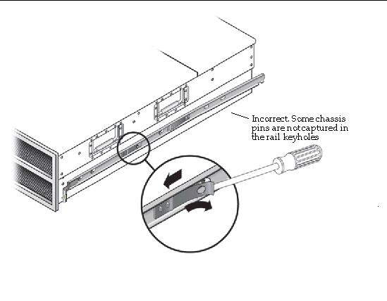
If some of the keyholes on the inner rail did not capture the chassis pins when you installed the inner rail to the chassis, do the following:
1. Lift the pin retaining latch as shown in FIGURE 1-8.
2. Push the inner rail forward (toward the front of the system) to remove it.
3. Then repeat steps 1 through 4 in the previous section to reinstall the rail.
FIGURE 1-8 Removing the Inner Rail from the Chassis
The following procedure explains how to install your Sun 4RU 48 HDD storage product (with the inner rails attached) into the slide-rail assemblies on the rack. This is a three-person operation.
1. Ensure that the inner rails are attached to either side of the system as described in the previous section.
2. Inspect the slide-rail assembly, and make sure that the middle rail ball bearing retainers are pulled to the front of both slide rails and secured with the green latch. See FIGURE 1-9.
3. Lift the system and bring the inner rails up to the entrance point on each side slide-rail assembly, keeping everything as level as possible. See FIGURE 1-9 and FIGURE 1-10.
FIGURE 1-9 Correct Setup for Inserting the System Into the Slide Rails
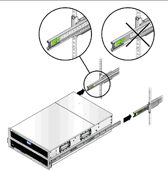
4. Press in on the green inner-rail release buttons on each of the slide rails (see the inset arrow labeled 3 in FIGURE 1-1). Slowly move the system in to engage the inner rails with the slide-rail assembly (see FIGURE 1-10).
| Note - Make sure the inner rails enter the middle rails at the correct angle, as shown in FIGURE 1-10. |
As you slide the system into the rack, a spotter or observer at the rear of the rack should make sure the inner rails are engaged with the ball-bearing retainers (shown in FIGURE 1-9) on both slide rails.
FIGURE 1-10 Making Sure Inner Rail Is Inserted at the Correct Angle
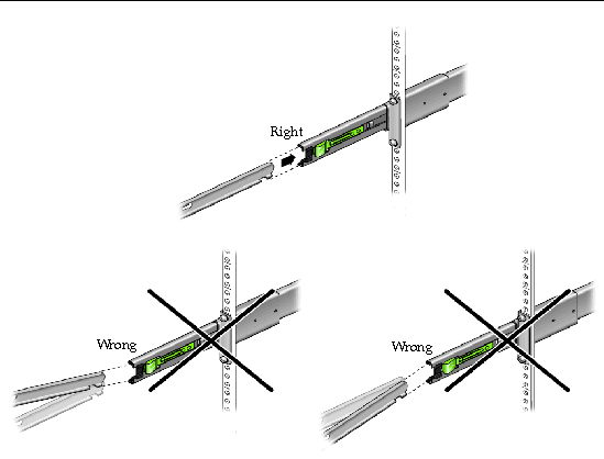
5. Slowly push the system all the way into the rack until the slide rail locks engage. There might be moderate resistance during the first insertion as the middle rails auto-adjust.
1. Slide out the system out to its service position by first releasing the latches on each side of the system, and then sliding it out until it reaches the stops. See the inset with arrows labeled 1 and 2 in FIGURE 1-11.
2. If you depopulated the system of hard disk drives during slide rail installation, replace them in the same locations from which they were removed.
3. Push in the green inner rail release button (with embossed arrow--see inset arrow labeled 3 in FIGURE 1-1) on each of the middle rails, and push the system all the way back into the rack until the slide rail locks engage.
4. If you removed power supplies or the system controller during slide rail installation, replace those in the same locations from which they were removed.
5. To complete the installation of your Sun rackable 4RU storage product, proceed to the installation instructions supplied with the product for the next steps. If you need to install a cable management assembly, proceed to the next section.
If a Cable Management Assembly (CMA) is supported for use with your Sun 4UR storage product, follow the instructions packaged with the CMA to properly install it. There are only certain Sun CMA products that may be used with the Sun X4500-J Slide Rails. Refer to your product documentation for a list.
This procedure assumes you have turned off the system, removed the cable management arm, and removed any cables or cords that would restrict the movement of the system.
1. If your system includes a cable management assembly (CMA), remove it and disconnect all the cables.
2. If you do not have a mechanical lift, remove the following components from the rear of the rack to reduce the weight to a safe level for manual lifting:
3. Slide out the system out to its service position by first releasing the latches on each side of the system, and then sliding it out until it reaches the stops. See the inset with arrows labeled 1 and 2 in FIGURE 1-11.
FIGURE 1-11 Releasing and Sliding out the System from the Rack
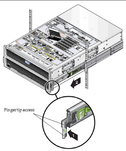
4. If you do not have a mechanical lift, open the hard disk drive access cover and remove the hard disk drives.

|
Caution - Make sure you label the drives so you can replace them in their original locations. |
5. To completely remove the system from the rack, do the following:
a. Press the green release lever (with embossed arrow) on each slide rail to disengage the system inner rails from the slide rail assembly (see the inset arrows labeled 1 and 2 in FIGURE 1-12).
b. Holding the handles located on each side of the system, slide the system completely out of the rack (see label 4 in FIGURE 1-12) and set it down on a clean, stable surface.
FIGURE 1-12 Removing the System from the Rack
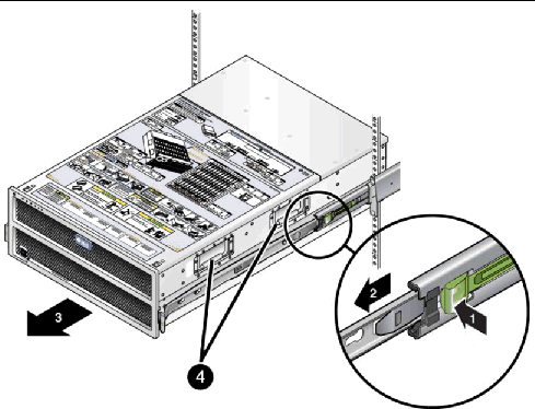
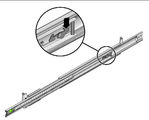
6. To prevent the middle rails from blocking access to the aisle as you service your system out of the rack, release the middle rail locks and then slide the middle rails back inside the outer rails. See FIGURE 1-13.
| Note - When reinstalling the system into the rack, first pull the middle rails back out to their locking position (see FIGURE 1-9) before attempting to reinsert the inner rails on the system into the middle and outer slide rails. |
FIGURE 1-13 Releasing the Middle Rail Lock
Copyright © 2009 Sun Microsystems, Inc. All rights reserved.