| Exit Print View | |
Sun Fire X4600 and Sun Fire X4600 M2 Servers Service Manual |

|
1. Introduction to the Sun Fire X4600/X4600 M2 Servers
2. Powering On and Configuring BIOS Settings
3. Maintaining the Sun Fire X4600/X4600 M2 Servers
A Sun Fire X4600 or X4600 M2 server supports up to 8 CPU modules. Each CPU module supports a single CPU and a number of memory DIMMs. This appendix describes the CPU modules available. It also gives procedures for populating CPU modules with DIMMs, populating the server with CPU modules, and using the diagnostic features built into each CPU module.
![]() F.1 CPU Module Models describes the CPU module models and explains the rules for populating the module with memory DIMMs.
F.1 CPU Module Models describes the CPU module models and explains the rules for populating the module with memory DIMMs.
![]() F.2 Populating a Server With CPU Modules describes the rules for populating a server with CPU modules and explains how module slot letters map to numeric module IDs.
F.2 Populating a Server With CPU Modules describes the rules for populating a server with CPU modules and explains how module slot letters map to numeric module IDs.
![]() F.3 Locating Faulty CPUs and DIMMs describes the CPU modules’ built-in diagnostic features.
F.3 Locating Faulty CPUs and DIMMs describes the CPU modules’ built-in diagnostic features.
This section describes the various CPU module models. Some models are available in multiple part numbers. All part numbers within a given model share basic features such as the kind of CPU they support and the way they use memory DIMMs. Individual part numbers vary as to the specific CPU they support. For more information refer to the Sun System Handbook:
http://sunsolve.sun.com/handbook_pub/
Each CPU module model description indicates whether it can be used with the X4600 server or the X4600 M2 server. No CPU module model can be used with both systems.
The sections that document individual CPU modules are:
This module is only compatible with the Sun Fire X4600 server. It supports an AMD Opteron 800 series dual-core CPU and a maximum of 8 GB of DDR1 memory.
Physical layout of the Sun Fire X4600 CPU Module is shown in ![]() Physical Layout of Sun Fire X4600 CPU Module.
Physical Layout of Sun Fire X4600 CPU Module.
Note - This module does not number its DIMM slots consecutively. Also, DIMM pairs are not placed in adjacent slots.
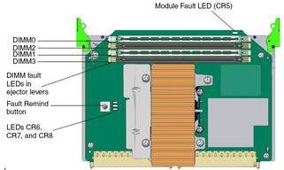
Pressing the Fault Remind button lights LEDs that indicate faulty CPU and DIMM.
See ![]() F.3 Locating Faulty CPUs and DIMMs.
F.3 Locating Faulty CPUs and DIMMs.
LEDs are described in ![]() Sun Fire X4600 CPU Module LEDs.
Sun Fire X4600 CPU Module LEDs.
|
The Sun Fire X4600 CPU Module provides four DIMM slots (![]() DIMM Slots in Sun Fire X4600 CPU Module), for
a maximum of two pairs. Here are the specifications and population rules used
with the DIMM slots:
DIMM Slots in Sun Fire X4600 CPU Module), for
a maximum of two pairs. Here are the specifications and population rules used
with the DIMM slots:
Type: DIMMs must be DDR1.
Speed: Maximum speed is 200 MHz (DDR1-400).
Capacity: 1-GB and 2-GB DIMMs are supported.
Matching: DIMMs must be added in pairs, with both DIMMs in a pair having the same Sun part number.
Slot Usage: Every module must have at least one matched pair of DIMMs. Populate pair 0 (the white slots) first.
|
This module is only compatible with the Sun Fire X4600 M2 server. It supports an AMD Opteron 8000 series dual-core CPU and a maximum of 16 GB of DDR2 memory.
Physical layout of the Sun Fire X4600 M2 4-DIMM CPU module is shown
in ![]() Physical Layout of Sun Fire X4600 M2 4-DIMM CPU M.
Physical Layout of Sun Fire X4600 M2 4-DIMM CPU M.
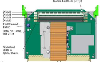
Pressing the Fault Remind button lights LEDs that indicate faulty CPU and DIMM.
See ![]() F.3 Locating Faulty CPUs and DIMMs.
F.3 Locating Faulty CPUs and DIMMs.
Note - This module can be used in the same system with Sun Fire X4600
M2 8-DIMM CPU modules, provided all CPUs are identical. For more information on
CPU module matching requirements, see ![]() F.2.1 CPU Module Matching Requirements.
F.2.1 CPU Module Matching Requirements.
LEDs are described in ![]() LEDs on Sun Fire X4600 M2 CPU 4-DIMM Module.
LEDs on Sun Fire X4600 M2 CPU 4-DIMM Module.
|
The Sun Fire X4600 M2 4-DIMM CPU module provides four DIMM slots (![]() DIMM Slots in Sun Fire X4600 CPU Module),
for a maximum of two pairs. Here are the specifications and population rules
used with the DIMM slots:
DIMM Slots in Sun Fire X4600 CPU Module),
for a maximum of two pairs. Here are the specifications and population rules
used with the DIMM slots:
Type: DIMMs must be DDR2.
Speed: Maximum speed is 333 MHz (DDR2-667).
Capacity: 1-GB, 2-GB, and 4-GB are supported on early CPU module card. 2-GB, 4-GB, and 8-GB DIMMs are supported on Split Plane CPU module card.
Matching: DIMMs must be added in pairs, with both DIMMs in a pair having the same Sun part number.
Slot Usage: Every module must have at least one matched pair of DIMMs. Populate pair 1 (the white slots) first.
|
These two modules have identical physical layout, and follow the same DIMM usage rules. They both are compatible with the Sun Fire X4600 M2 server only. They have important differences:
The Sun Fire X4600 M2 8-DIMM CPU module supports a dual-core AMD Opteron 8000 series CPU. It can be used in the same system with Sun Fire X4600 M2 4-DIMM CPU modules, provided all CPUs are identical. It supports a maximum of 32-GB of DDR2 memory.
The Sun Fire X4600 M2 8-DIMM Split Plane CPU module supports a quad-core AMD Opteron 8000 series CPU. Quad core is only supported on the Split Plane CPU module. When this model is used a system, all CPU modules must have the same Sun part number. It supports a maximum of 64-GB of DDR2 memory.
Note - For more information on CPU module matching requirements, see ![]() F.2.1 CPU Module Matching Requirements.
F.2.1 CPU Module Matching Requirements.
Physical layout of the Sun Fire X4600 M2 8-DIMM and 8-DIMM split plane
CPU modules is shown in ![]() Physical Layout of Sun Fire X4600 M2 4-DIMM CPU M.
Physical Layout of Sun Fire X4600 M2 4-DIMM CPU M.
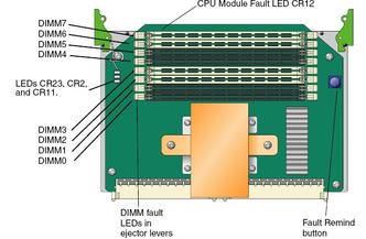
Pressing the Fault Remind button lights LEDs that indicate faulty CPU and DIMM.
See ![]() F.3 Locating Faulty CPUs and DIMMs.
F.3 Locating Faulty CPUs and DIMMs.
LEDs are described in ![]() LEDs on Sun Fire X4600 M2 CPU 4-DIMM Module.
LEDs on Sun Fire X4600 M2 CPU 4-DIMM Module.
|
The Sun Fire X4600 M2 8-DIMM and 8-DIMM split plane CPU modules provides
8 DIMM slots (![]() Sun Fire X4600 M2 8-DIMM and 8-DIMM split plane CPU Module DIMM Slots), for a maximum of four pairs. Here are the
specifications and population rules used with the DIMM slots:
Sun Fire X4600 M2 8-DIMM and 8-DIMM split plane CPU Module DIMM Slots), for a maximum of four pairs. Here are the
specifications and population rules used with the DIMM slots:
Type: DIMMs must be DDR2.
Speed
8-DIMM with 2 or 4 DIMMs: Maximum speed is 333 MHz (DDR2-667).
8-DIMM with 6 or 8 DIMMs: Maximum speed is 266 MHz (DDR2-533).
8-DIMM split plane CPU module: Maximum speed is 333 MHz (DDR2-667).
Capacity: 1-GB, 2-GB, and 4-GB DIMMs are supported.
Matching: DIMMs must be added in pairs, with both DIMMs in a pair having the same Sun part number.
Slot Usage: Every module must have at least one matched pair of DIMMs. Populate pair 3 (the white slots farthest from the CPU) first, and work your way towards the CPU.
|
Note - This section describes configurations with 2, 4, 6, and 8 CPU modules. The number of modules a system can actually support depends on the software and firmware versions. To identify the configurations supported by your system, see the Software Release Notes for the system software you have installed.
The following CPU modules can be used together:
Sun Fire X4600 M2 4-DIMM CPU module
Sun Fire X4600 M2 8-DIMM CPU module
Except for the modules listed in this section, all CPU modules in a server must be identical. This means that each module must have the same Sun part number. If two modules are the same model but different part numbers, then their CPUs are different; mixing CPUs in a single server is not supported.
When different CPU modules are in the same system, the CPUs must be identical. This means that even though the part numbers for the CPU modules may be different, the part numbers for the CPUs on the modules must be the same.
Mixed four Sun Fire X4600 M2 8-DIMM CPU modules plus four Sun Fire X4600 M2 8-DIMM Split Plane CPU modules with 8220 Series processors on a Sun Fire X4600 server requires a 950w PSU.
The Sun Fire X4600 M2 8-DIMM CPU module is an 8-DIMM CPU board that supports AMD Opteron 8000 Series Rev. F dual-core processors.
The Sun Fire X4600 M2 8-DIMM Split Plane CPU module is an 8-DIMM CPU board that supports AMD Opteron 8000 Series Rev. F quad-core processors.
 | Caution - Only the CPU modules listed in this section can used together. |
The 8 CPU module slots are designated by letters A through H, as
shown in ![]() Sun Fire X4600/X4600 M2 CPU Module Slots. Looking from the front of the server, the CPU module
slots are lettered from right to left.
Sun Fire X4600/X4600 M2 CPU Module Slots. Looking from the front of the server, the CPU module
slots are lettered from right to left.
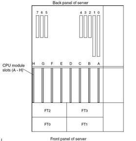
When a server contains fewer than 8 CPU modules, only specific slots can
be used, as shown in ![]() CPU Module Population rules and numbering. This figure also shows how the CPU module
slot letters map to the numbers that identify actual CPU modules.
CPU Module Population rules and numbering. This figure also shows how the CPU module
slot letters map to the numbers that identify actual CPU modules.
Note - In an eight-module configuration, the modules are not all in numerical order. Slot B contains module 2, and slot C contains module 1.
Note - In a two-module configuration, use of PCI slots 5, 6, and 7 is not supported.
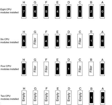
Note - In six-module and four-module configurations, unused CPU slots must contain filler modules. In two-module configurations, unused CPU slots must be left empty.
Every CPU module supports the following diagnostic procedure.
Make sure that the system is powerd down, but that power cables are still connected to the PSU. This ensures that standby power is flowing to the CPU modules
Locate the CPU module with a lit amber LED visible at its top edge. The LED indicates that the module has faulty CPU or DIMM.
Remove standby power by disconnecting all power cables from the PSU.
 | Caution - Removing or inserting a CPU module while standby power is available can damage the module. |
Remove the CPU module you previously identified from its slot in the CPU module bay. See ![]() Replacing a CPU Module or CPU Filler Board.
Replacing a CPU Module or CPU Filler Board.
Press the module’s fault remind button. If a DIMM is faulty, an amber LED is lit in one of the DIMM’s slot handles. If the CPU is faulty, a CPU fault LED is lit. These LEDs are powered by an on-board capacity and can remain lit about a minute.
To identify the fault remind button and the CPU fault LED, refer to
the individual module descriptions in ![]() F.1 CPU Module Models.
F.1 CPU Module Models.