| C H A P T E R 1 |
|
Installation |
The Sun StorEdge 2 Gb FC PCI Dual Channel Network Adapter Installation Guide describes how to install the Sun StorEdge 2G FC PCI Dual Channel Network Adapter card in a system. These instructions are designed for an experienced system administrator or trained service provider.
Please refer to the Release Notes for the complete list of Operating System support (for example, Solaris x86, Linux and Windows) on this HBA. The minimum Solaris SPARC operating environment releases to support the device drivers for the Sun StorEdge 2G FC PCI Dual Channel Network Adapter card is Solaris 8 update 4.
All of the drivers are unbundled with Solaris 8 SPARC operating environmen. See the Sun StorEdge 2G FC PCI Dual Channel Network Adapter Product Notes for a list of packages and patches and instructions for downloading them.
|
Note - If the required packages and patches are note installed, you can not use the network adapter. |
You may need to order fiber optic cables. You can order them in the following lengths:

|
Caution - Damage to the HBA can occur as the result of careless handling or electrostatic discharge (ESD). Always handle the HBA with care to avoid damage to electrostatic sensitive components. |
To minimize the possibility of ESD-related damage, Sun strongly recommends using both a workstation antistatic mat and an ESD wrist strap. You can get an ESD wrist strap from any reputable electronics store or from Sun as part number #250-1007. Observe the following precautions to avoid ESD-related problems:
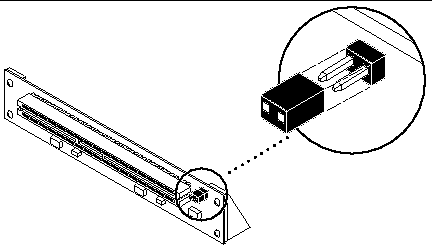
The Sun StorEdge 2G FC PCI Dual Channel Network Adapter card does not support JTAG. When you install the PCI host adapter in a Sun Enterprise system, be sure that the corresponding PCI riser card has the JTAG jumper removed (FIGURE 1-1).
|
Note - If the JTAG jumper is installed, the PCI I/O board will not be recognized or initialized during POST (power-on self-test) nor will it subsequently be recognized by the operating system. |

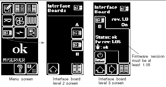
1. Use the array's front panel module (FPM) to ensure that the firmware level of the interface boards is at least 1.05.

If the firmware level is less than 1.05, you must upgrade the firmware using an
SBus-based host system before you can connect the array to the Sun StorEdge PCI Dual Fibre Channel Host Adapter. The instructions for obtaining the upgrade patch are in Step 3.
2. Determine which version of the Solaris operating environment you are using.
Look at the /etc/release file and make sure the operating environment installed is at least Solaris 8. If you do not have an /etc/release file, you probably need to upgrade you operating environment to at least Solaris 8.
a. Go to the http://docs.sun.com Web site and read the Sun StorEdge A5000 Installation Supplement.
b. Go to the http://www.sun.com/products-n-solutions/hardware/docs Web site, click Storage and read the Sun StorEdge 2G FC PCI Dual Channel Network Adapter Product Notes for the software patch IDs.
c. Download the software patches from the URL listed in the Sun StorEdge 2G FC PCI Dual Channel Network Adapter Product Notes or, for updates, go to: http://sunsolve.sun.com.
Contact your support service provider if you cannot access these Web sites.
|
Note - Be sure to read and follow the directions in the README file for each patch. |
4. Log in as root on your system.
5. Verify that the SUNWses, SUNWssad, and SUNWvts packages have been installed on your system.
Use the /usr/bin/pkginfo command and grep for each of the above patches. For example:
If you are missing any of these patches, you can get them from the Updates for
Solaris Operating Environment of your Solaris operating environment distribution.
6. Exit the operating environment.
To inform any mounted users that the system will be going down, use the shutdown command. Otherwise, use the init 0 command. See the Man Pages for these commands or the Solaris AnswerBook online documentation.
Refer to the service documentation that came with your system.

|
Caution - Do not disconnect the power cord at this time. This connection provides the ground path necessary to remove and install printed circuit boards and components without damage. |
8. Choose a slot into which to install the host adapter.
Follow the procedures in the documentation supplied with your system.
For systems that have more than one system board, you must also select and remove a system board that has an available PCI slot. Refer to your system documentation for specific instructions.
9. Attach the antistatic wrist strap to your wrist and to a metal component on the system chassis.
The wrist strap between you and the chassis provides the ground path necessary to safely remove and install the printed circuit boards and components without damaging them.
10. For systems with a standby-type power switch, disconnect the power cord.
Standby-type power switches have a  icon.
icon.
Refer to your system documentation for specific instructions.

|
Caution - If you need to remove a system board for installation, place the board on a padded antistatic mat to prevent damage. |
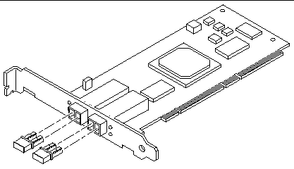
1. Pull the two dust covers out of the 2x5 optical transceiver (OT) connectors (FIGURE 1-3).

2. Install the host adapter in the PCI slot you have chosen.
Installation details vary for each system. Refer to your system documentation for specific instructions.
Refer to your system documentation for specific instructions.
4. Disconnect the wrist strap.
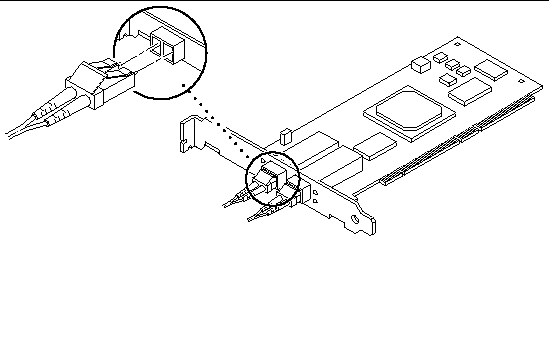
5. Push the fiber optic cable connector into the OT connector until you hear a click (FIGURE 1-4).

|
Caution - Fiber optic cables have keyed connectors; they can only be inserted into OT connectors as shown in FIGURE 1-4. |

6. Connect the other end of the fiber optic cable to a device such as an array, switch or hub.
Refer to the documentation that came with the device for specific instructions.
7. Power on your peripherals and then your system.
|
Note - When you power on the system, the LED lights on the host bus adapter might blink. The LEDs are intended for manufacturing use only. |
|
Note - If your system starts to reboot, interrupt the reboot process by pressing the Stop-A keys. |
The system should now be at the ok prompt. If a > prompt is showing, type n to switch to the ok prompt.
8. Make sure that the system recognizes the host adapter.
See FIGURE 1-5 on "Invalid Cross-Reference Format" and "Invalid Cross-Reference Format". "Invalid Cross-Reference Format" is a continuation of "Invalid Cross-Reference Format".
In "Invalid Cross-Reference Format", /pci@e,0/pci@1/pc1@1/SUNW,qlc@5 is one port on the Sun StorEdge 2G FC PCI Dual Channel Network Adapter and the disks are in a Sun StorEdge A5000 array (SENA).
9. Reboot your system using the boot -r command.
Refer to the SunVTS documents in TABLE 1-4.
|
SunVTS 4.5 User's Guide[1] |
||
|
SunVTS 4.3 User's Guide[2] |
||
SunVTS is a diagnostic program that exercises your system to verify the functionality, reliability, and configuration of your host adapter. You will need to install both the 32- and 64-bit versions of SunVTS.
1. To invoke SunVTS locally on a system running CDE, type the following as root:
2. From the SunVTS menus select the following:
a. Select devices None and select intervention.
b. Select mode Functional test.
c. Select HostAdapters qlcx where x is the qlc number of the qlc port you want to run this test against.
d. If you want to run the external loopback test, place a loopback plug into the qlc port that you want to test.
If you do not have an external loopback plug, you can make one by taking apart a fiber cable and plug the same cable into the transmitter and receiver of the qlc port.
e. Right click on the qlc test and select Test Parameter Options.
f. Enable the External Loopback Test.
|
Note - If you do not use a loopback plug, you can connect the qlc port to storage devices. In such a case, you will be testing both the qlc and the entire fiber loop. |
g. Select Start to start the test.
Copyright © 2007, Sun Microsystems, Inc. All Rights Reserved.