| A P P E N D I X A |
|
Sun XVR-100 Graphics Accelerator I/O Port Specifications |
This appendix provides I/O port specifications for the Sun XVR-100 graphics accelerator.
The external I/O ports are accessible through the I/O connectors on the Sun
XVR-100 graphics accelerator back panel (FIGURE A-1).
FIGURE A-1 shows the connector locations on the board back panel.
FIGURE A-1 Sun XVR-100 Graphics Accelerator Back Panel I/O Ports

The Sun XVR-100 graphics accelerator I/O video ports include the HD15 and DVI video ports.
FIGURE A-2 and TABLE A-1 shows the Sun XVR-100 graphics accelerator HD15 connector and pinout signals.
The console video output port is the HD15 15-pin connector that connects to the workstation monitor. The HD15 video connector supports DDC2 monitor support and Display Power Management Signaling (DPMS).
FIGURE A-2 Sun XVR-100 Graphics Accelerator HD15 Connector

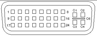
FIGURE A-3 and TABLE A-2 shows the Sun XVR-100 graphics accelerator DVI connector and pinout signals. The DVI video output port is a 30-pin connector for a supported workstation monitor. The DVI video port supports both analog and digital resolutions, but cannot be used simultaneously from the individual DVI port.
FIGURE A-3 Sun XVR-100 Graphics Accelerator DVI Connector

Copyright © 2008, Sun Microsystems, Inc. All Rights Reserved.