| Sun XVR-300 Graphics Accelerator User's Guide
|
   
|
Sun XVR-300 Graphics Accelerator Specifications
|
This appendix provides the Sun XVR-300 graphics accelerator product specifications.
Board Specifications
This graphics accelerator is for use with UL Listed ITE that have installation instructions detailing user installation of card cage accessories.
TABLE B-1 lists the product specifications.
TABLE B-1 Sun XVR-300 Graphics Accelerator Specifications
|
Parameter
|
Specification
|
|
|
Weight
|
3.7 oz (105 grams)
|
|
|
Length
|
6.6 in. (165mm)
|
|
|
Width
|
2.3 in. (55mm)
|
|
|
Power specification
|
5.0 V +/- 5%
3.3 V +/- 5%
12 V +/- 5%
VDDQ V +/- 5%
|
|
|
Current consumption
|
5V
3.3V
12V
VDDQ V
|
|
|
Temperature
|
Power-on: 10° to 50° C
Power-off: 0° to 70° C
(storage/transport)
|
|
|
Humidity
|
Power-on: 5 to 90% RH
Power-off: 0 to 95% RH
|
|
|
Temperature gradient
|
Less than 15° C/hr
|
|
DMS-59 Video Port
FIGURE B-1 shows the Sun XVR-300 graphics accelerator DMS-59 video port.
FIGURE B-1 Sun XVR-300 Graphics Accelerator DMS-59 Video Port

DMS-59 Connector Pinouts
FIGURE B-2 and TABLE B-2 shows the DMS-59 connector and pinout signals.
FIGURE B-2 DMS-59 Connector

TABLE B-2 Sun XVR-300 Graphics Accelerator DMS-59 Pinout
|
Pin
|
Signal
|
|
1
|
Ground
|
|
2
|
A_R_DAC1_F
|
|
3
|
A_B_DAC1_F
|
|
4
|
Ground
|
|
5
|
+5_VESA
|
|
6
|
DDCCLK_DAC1_R
|
|
7
|
DDCDATA_DAC1_R
|
|
8
|
Ground
|
|
9
|
DDCDATA_DAC2_R
|
|
10
|
DDCCLK_DAC2_R
|
|
11
|
+5_VESA2
|
|
12
|
Ground
|
|
13
|
A_R_DAC2_F
|
|
14
|
A_B_DAC2_F
|
|
15
|
Ground
|
|
16
|
TMDS_TX0P
|
|
17
|
TMDS_TX0N
|
|
18
|
TMDS_TX1P
|
|
19
|
TMDS_TX1N
|
|
20
|
TMDS_TX2P
|
|
21
|
TMDS_TX2N
|
|
22
|
Ground
|
|
23
|
No Connect
|
|
24
|
Ground
|
|
25
|
TX2P_EXT
|
|
26
|
TX2M_EXT
|
|
27
|
TX1P_EXT
|
|
28
|
TX1M_EXT
|
|
29
|
TX0P_EXT
|
|
30
|
TX0M_EXT
|
|
31
|
TXCP_EXT
|
|
32
|
TXCM_EXT
|
|
33
|
Ground
|
|
34
|
Ground
|
|
35
|
Ground
|
|
36
|
HPD_ExtTMDS_LFH
|
|
37
|
No Connect
|
|
38
|
Ground
|
|
39
|
No Connect
|
|
40
|
HPD_DMS59
|
|
41
|
Ground
|
|
42
|
Ground
|
|
43
|
Ground
|
|
44
|
TMDS_TXCN
|
|
45
|
TMDS_TXCP
|
|
46
|
Ground
|
|
47
|
A_G_DAC2_F
|
|
48
|
No Connect
|
|
49
|
Ground
|
|
50
|
A_HSYNC_DAC2_R
|
|
51
|
A_VSYNC_DAC2_R
|
|
52
|
Ground
|
|
53
|
No Connect
|
|
54
|
Ground
|
|
55
|
A_VSYNC_DAC1_R
|
|
56
|
A_HSYNC_DAC1_R
|
|
57
|
Ground
|
|
58
|
No Connect
|
|
59
|
A_G_DAC1_F
|
|
60
|
Ground
|
DVI Connector Pinouts
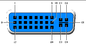
FIGURE B-3 and TABLE B-3 shows the DVI connector and pinout signals of the
2xDVI-I adapter splitter cable.
FIGURE B-3 DMS-59 - 2xDVI-I Adapter Splitter Cable DVI Connector

TABLE B-3 DVI Video Cable Connector Pinout
|
Pin
|
Signal
|
|
1
|
TMDS Data2--
|
|
2
|
TMDS Data2+
|
|
3
|
TMDS Data2/4 Shield
|
|
4
|
No Connect
|
|
5
|
Ground
|
|
6
|
DDC clock
|
|
7
|
DDC data
|
|
8
|
Analog VSYNC
|
|
9
|
TMDS Data1-
|
|
10
|
TMDS Data1 +
|
|
11
|
TMDS Data1/3 Shield
|
|
12
|
No Connect
|
|
13
|
No Connect
|
|
14
|
+5V Power
|
|
15
|
Ground
|
|
16
|
Hot-Plug Detect
|
|
17
|
TMDS Data0-
|
|
18
|
TMDS Data0+
|
|
19
|
TMDS Data0/5 Shield
|
|
20
|
No connect
|
|
21
|
No connect
|
|
22
|
TMDS Clock Shield
|
|
23
|
TMDS Clock+
|
|
24
|
TMDS Clock-
|
|
C1
|
Analog R
|
|
C2
|
Analog G
|
|
C3
|
Analog B
|
|
C4
|
Analog HSYNC
|
|
C5
|
Analog GND
|
HD15 (VGA) Connector Pinouts
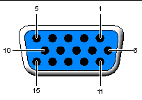
FIGURE B-4 and TABLE B-4 shows the HD15 (VGA) adapter connector and pinout signals.
FIGURE B-4 HD15 (VGA) Connector

TABLE B-4 HD15 (VGA) Connector Pinout
|
Pin Number
|
Signal
|
|
1
|
Red analog video
|
|
2
|
Green analog video
|
|
3
|
Blue analog video
|
|
4
|
No Connect
|
|
5
|
Ground
|
|
6
|
Ground
|
|
7
|
Ground
|
|
8
|
Ground
|
|
9
|
+5V Supply
|
|
10
|
Ground
|
|
11
|
No Connect
|
|
12
|
Monitor ID1
|
|
13
|
Horizontal Sync
|
|
14
|
Vertical Sync
|
|
15
|
Monitor ID2
|
| Sun XVR-300 Graphics Accelerator User's Guide
|
819-6651-13
|
   
|
Copyright © 2007, Sun Microsystems, Inc. All Rights Reserved.


