| Sun Ultra 45 and Ultra 25 Workstations Service and Diagnostics Manual |
| Sun Ultra 45 and Ultra 25 Workstations Service and Diagnostics Manual |
| C H A P T E R 6 |
|
Finishing Component Replacement |
This chapter describes how to finish the replacement of internal workstation replaceable components, close the system, and prepare it for operation. Topics covered in this chapter are:
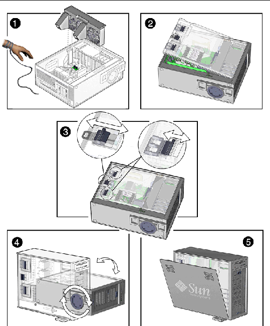
1. Verify that you have not left any tools, loose screws, or loose components inside the system.
2. Replace the fan tray if you removed it (FIGURE 6-1).
3. Fit the access panel into the chassis (FIGURE 6-1).
a. Ensure that the access panel latches are secure.
b. Slide the lock block towards the back of the workstation.
If desired, lock the system or insert a security cable.
4. Remove the wrist strap from the workstation and your wrist.
5. Pivot the support stabilizer from underneath the workstation (FIGURE 6-3).
7. Press in the side cover until the latches click.
8. Reconnect the keyboard, mouse, monitor, network connections, and any peripherals (FIGURE 6-2).
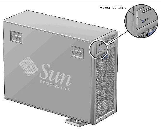
9. Reconnect the power cord to the workstation and the power source.
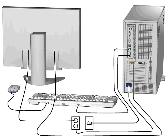
10. Power on any connected peripherals or monitors.
|
Note - The monitor must be powered on before the workstation so that the monitor can communicate with the graphics accelerator when the workstation powers on. |
For most component installations you should become superuser and reboot the workstation so that the Solaris OS finds the new component.
If you are at the ok prompt, type:
There are several methods for verifying the installation of the new component.
1. Boot the system with the -r option, so that the Solaris OS can reconfigure itself for the new component.
If a warning message is displayed, refer to Section 12.4, OpenBoot PROM Messages.
3. If the problem has not been solved, see Diagnostics Hierarchy.
1. Run POST with the diag-switch to true and the diag-level set to max.
2. Verify that the new device is recognized by POST.
Refer to Power-On Self-Test.
Use OpenBoot Diagnostics to test all devices. Refer to OpenBoot Diagnostics.
From a terminal window, type prtdiag and verify that all the correct devices are recognized by the system. Refer to prtdiag Command.
| Sun Ultra 45 and Ultra 25 Workstations Service and Diagnostics Manual | 819-1892 |
Copyright © 2006, Sun Microsystems, Inc. All Rights Reserved.