 To Remove the Heat Sink and CPU
-
Power off the workstation using the procedure described in the section, To Power Off the Workstation.
-
Remove the left-side access panel using the procedure described in the section, To Remove the Left-Side Access Panel.
-
Gently lay the system on its right side on a stable, nonslip surface.
-
Disconnect the heat sink’s CPU fan cable from its connector on the motherboard.
The CPU fan connector is labeled CPU_FAN.
-
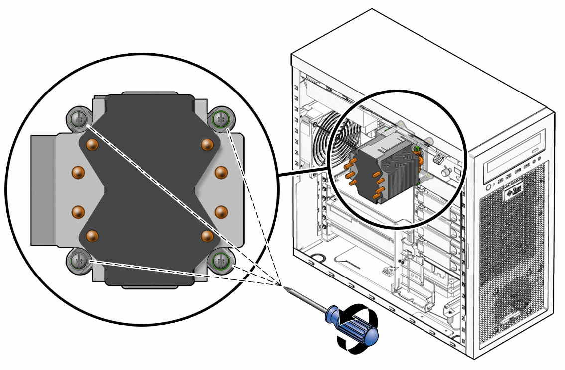
Remove the heat sink assembly by alternately loosening (2-3 turns) the four captive screws that secure the heat sink assembly to the motherboard. Continue loosening each screw until all the screws are no longer securing the heat sink (see Figure 3–31).
The heat sink assembly is also mounted to the top surface of the CPU by a layer of thermal compound.
Figure 3–31 Removing the Heat Sink-Fan Assembly

-
Grasp the heat sink by its plastic mounting bracket, and, while gently pulling upward, slowly wiggle the assembly back and forth to break the adhesive seal of the thermal compound.
-
Remove the heat sink-fan assembly from the chassis.
-
Place the heat sink on its side and on a flat surface to prevent the thermal compound from contaminating other components and the work space.
-
Depress the CPU socket retainer lever and slightly pull the lever outward (away from the CPU) to free the lever from its retaining clip (see Figure 3–32).
-
When you have released the lever from the retaining clip, lift the lever to its fully open (upright) position.
This action releases the pressure on the hinged CPU socket retainer. The top of the CPU has some residual thermal compound.
-
Lift the unhinged side of the CPU socket retainer to its fully open (upright) position.
This action exposes the CPU. The CPU is mounted to a PCB that is keyed (notched) on two opposite sides.
Figure 3–32 Removing the CPU From the Workstation

-
Grasp the notched edges of the CPU PCB and lift it out of the socket.
Set the CPU on an antistatic mat or surface.
-
Remove the new CPU from the antistatic packaging.
-
Ensure that the CPU socket retainer lever and hinged socket retainer are in the fully open (upright) position (see Figure 3–33).
-
Remove the new CPU from its antistatic packaging.
The CPU is mounted on a PCB that is notched on two opposite sides.
-
Hold the CPU by its notched sides.
-
Position the CPU over the CPU socket so that the notches on the PCB align with the keys on the socket.
 Caution –
 Irreparable damage to the motherboard can occur if downward force is applied to the socket. Do not force the CPU into the socket.
-
Carefully set the CPU onto the socket.
When correctly positioned the CPU lies flat in the socket, and the notches on the CPU are aligned with the keys on the socket, restricting movement of the CPU within the socket.
Figure 3–33 Installing the CPU

-
When the CPU is positioned in the socket, lower the hinged socket retainer.
-
Lower the socket retainer lever, pressing it downward, and secure it under the lever retaining clip.
-
Do this step only if you are installing a new CPU. If you are installing a used CPU, go to Step 22.
-
Gently wipe the top of surface of the CPU, using the supplied alcohol wipe, and allow to dry.
The heat sink assembly has thermal compound pre- applied. Do not apply additional thermal compound to the top of the CPU. The thermal compound on the heat sink is protected by plastic cover.
-
Remove the plastic cover that protects the thermal compound on the bottom of the heat sink assembly.
-
Go to Step 23.
-
-
Do this step if you are installing an already-used CPU onto a new motherboard. Otherwise, go to Step 23.
-
Use an alcohol-soaked wipe to remove the thermal compound from the top of the CPU and the bottom of the heat sink.
-
Use the supplied syringe to apply approximately 0.5 ml of thermal compound in a star pattern to the center of the top of the CPU.
Use the entire contents of the syringe.
-
Using the clean edge of a plastic bag, spread the thermal compound until it covers the top of the CPU in a thin, uniform layer.
 Caution –
 Do not use an unprotected finger to spread the thermal grease. The oil on your finger will degrade the performance of the thermal grease.
-
-
Inspect the heat sink-fan assembly for dust and lint. Clean if necessary.
-
Carefully position the heat sink-fan assembly over the CPU so that the arrow on the top points toward the front of the workstation.
-
Align the four captive screws on the heat sink assembly with the holes in the motherboard.
-
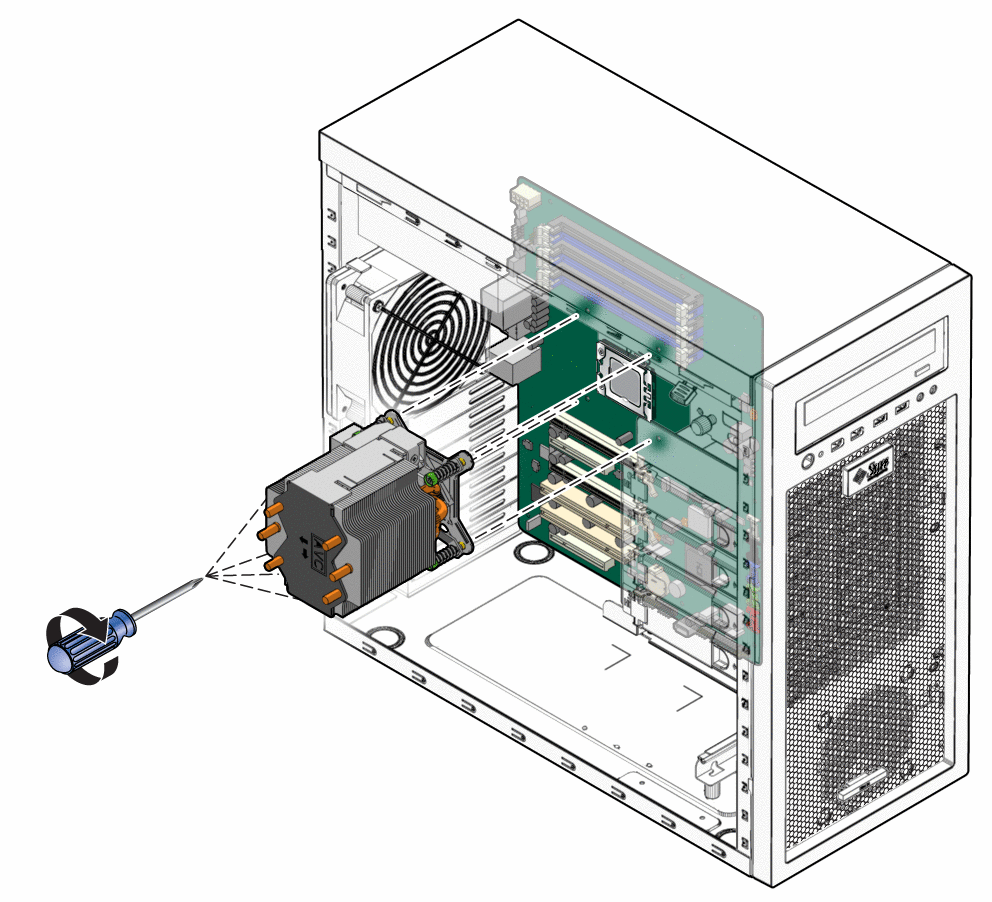
Lower the heat sink-fan assembly onto the top of the CPU, avoiding any side-to-side movement. See Figure 3–34.
Figure 3–34 Installing the Heat Sink-Fan Assembly

 Caution –
 If you move the heat sink assembly too much during installation, the layer of thermal grease might not be distributed evenly, leading to component damage.
-
Press down slightly on the top of the heat sink-fan assembly while alternately tightening (3–5 turns) each of the four screws.
Continue doing this until the heat sink-fan assembly is secured to the motherboard and you can no longer tighten the screws.
 Caution –
 Irreparable damage can occur to the motherboard if you attempt to overtighten the heat sink-fan assembly screws.
-
Connect the heat sink cable to the connector on the motherboard.
-
Close the workstation and prepare for operation using the procedures described in the section, Closing the Workstation and Preparing for Operation.
- © 2010, Oracle Corporation and/or its affiliates
