Chapter 1 Sun Ultra 27 Workstation Hardware Features
This chapter provides an overview of the Sun Ultra 27 workstation hardware features, and includes the following sections:
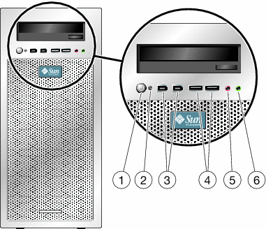
Front Panel
Figure 1–1 Front Panel
|
Figure Legend |
|||
|---|---|---|---|
|
1 |
Power button |
2 |
Power LED |
|
3 |
1394 ports (2) |
4 |
USB 2.0 ports (2) |
|
5 |
Microphone-in jack |
6 |
Headphone-out jack |
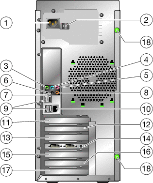
Back Panel
Figure 1–2 Back Panel
|
Figure Legend |
|||
|---|---|---|---|
|
1 |
AC power connector |
2 |
Power switch |
|
3 |
Audio jack (green) |
4 |
Line-in jack (blue) |
|
5 |
Mic jack (pink) |
6 |
Side audio connector (gray) |
|
7 |
Back audio connector (black) |
8 |
Center audio connector (orange) |
|
9 |
Four USB 2.0 ports |
10 |
Ethernet connector |
|
11 |
Cover plate (no slot) |
12 |
Slot 0, PCIe 2 x16 |
|
13 |
Slot 1, PCIe 2 x8 mech./x4 elec. |
14 |
Slot 2, PCIe 2 x16 |
|
15 |
Slot 3, PCIe x1 |
16 |
Slot 4, PCI 33 Mhz, 32–bit |
|
17 |
Slot 5, PCIe x8 mech./x4 elec. |
18 |
Thumbscrews (side cover) |
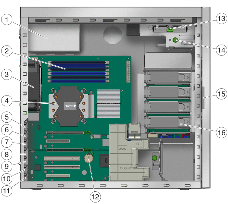
Internal Components and Cables
Figure 1–3 Internal Components
|
Figure Legend |
|||
|---|---|---|---|
|
1 |
Power supply |
2 |
DIMM slots (6) |
|
3 |
System fan |
4 |
Heat sink and CPU |
|
5 |
Blank unused slot |
6 |
Slot 0, PCIe2 x16 |
|
7 |
Slot 1, PCIe2 (x8 mechanical, x4 electrical) |
8 |
Slot 2, PCIe2 x16 |
|
9 |
Slot 3, PCIe x1 |
10 |
Slot 4, PCI 33 MHz, 32–bit slot |
|
11 |
Slot 5, PCIe (x8 mechanical, x4 electrical) |
12 |
System battery |
|
13 |
DVD release latch |
14 |
I/O release screw (captive) |
|
15 |
Serial number |
16 |
Hard drives (4 max.) |
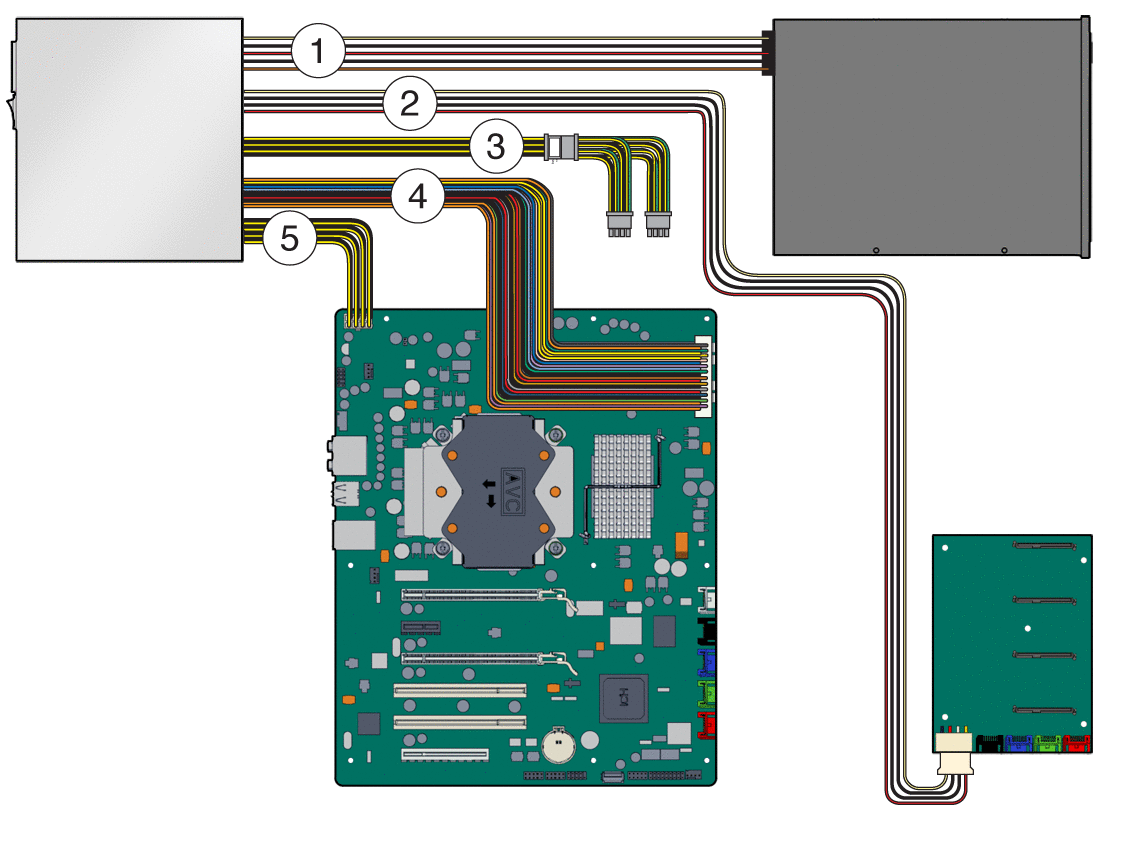
Power Supply Cables and Connections
Figure 1–4 Power Supply Cables and Connections
|
Figure Legend |
|||
|---|---|---|---|
|
1 |
DVD power (P3, 4–pin and P5 15–pin) |
2 |
Disk storage backplane (P4 connects to J5) |
|
3 |
Supplemental power cable (labeled PCI and To Gfx Card or Splitter) connects to PCIe card |
4 |
P1 motherboard (PWR1 connects to PWR1) |
|
5 |
P2 motherboard (P2 connects to PWR2) | ||
Component Cables and Connections
Figure 1–5 Component Cables and Connections
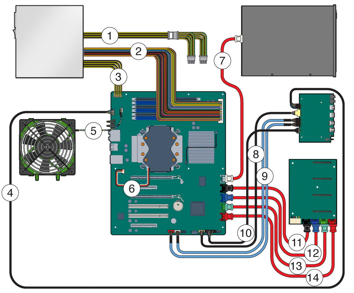
|
Figure Legend |
|||
|---|---|---|---|
|
1 |
Supplemental power cable (for PCIe cards) |
2 |
Power supply P1 to MB PWR1 |
|
3 |
Power supply P2 to MB PWR2 |
4 |
I/O board J1 to MB FPB_Audio |
|
5 |
System fan to MB SYS_FAN |
6 |
CPU fan to MB CPU_FAN |
|
7 |
DVD to MB SATA 0 (white) |
8 |
I/O board J5 to MB FPB_USB |
|
9 |
I/O board J8 to MB 13940-0 and 1394-1 |
10 |
I/O board J12 to MB FPB_CONN |
|
11 |
SATA 1 to storage backplane HDD0 (black) |
12 |
SATA 2 to storage backplane HDD1 (blue) |
|
13 |
SATA 3 to storage backplane HDD2 (green) |
14 |
SATA 4 storage backplane HDD3 (red) |
- © 2010, Oracle Corporation and/or its affiliates
